You quickly get used to good things and when breaks down central locking , then there is no need to delay the repair. You can determine the causes of the breakdown by the symptoms and in most cases do-it-yourself central lock repair does not work. However, in some cases solve the problem of central lock can only be replaced.
As install a central lock in the VAZ 2110 I will not tell, because detailed instructions are in the VAZ 2110 documentation (wiring diagram for the VAZ 2110 central lock), but I'll try visually show the various breakdowns of the electric lock and ways to solve them.
Central lock (CZ) or otherwise electronic lock consists of an activator (actuator, electric door lock), wiring, traction. Therefore, if you have electric lock broken and not working, then the problem lies in these components.
The VAZ 2110 can use various activators. They can differ in effort, small design features, manufacturer / country, etc., but they have a similar principle of operation: 


The principle of operation of the activator of the central lock
To understand why is the electric lock not working, you should consider the principle of its work:
 |
Five-wire activator with cover removed. Above the activator lies anther. Two wires of the activator are connected to the electric motor. The remaining three wires are connected to the limit switch. |
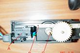 |
In this photo, a fragment with the image of the limit switch is enlarged, it is marked with the letter "A". "B" - stem shank in extended position. "C" - the motor shaft with a gear mounted on it. |
 |
"A" - rod in the extended state. "B" - damper rubber rings. They protect the stem and body from breakage upon impact in the extreme positions of the stem. |
It is not correct to check the operation of the activator without rigid fixation (without fastening on the door) and without connecting the rod, because
after actuation in the extreme retracted or extended position, the stem will bounce in the opposite direction.
Power Steering Vaz With Us You Will Find Any Auto Parts At Favorable Prices For Your Car! avtobazar.ua
Problems in the operation of the central lock
Consider the moment when the driver closes the car, the doors close and immediately open.
 |
If we consider this case in detail, it turns out that the stem is almost completely retracted, and the limit switch is in a borderline state (it may or may not be pressed). The limit switch will send a command to the central locking module and the rest of the doors will also close, but as a result of a slight deformation of the door or mechanism (for example, a slight blow to the car, heating / cooling of the door metal, etc.) - the limit switch can switch back and the central lock will open. The defect may appear when the door is closed, when the standard mechanism springs the rod and, accordingly, the stem to the opposite position and the doors open again. |
To make sure that this is the problem of the central lock in your case, you need to turn on the alarm while sitting in the car and try to press the door lock button down to hold with your hand (to prevent a springy defect in the mechanism). If the doors do not open, then this is the above-described defect in the mechanism for adjusting and attaching the activator and its thrust.
Why is there no such problem of the central lock on foreign cars?
Because there the command to open the lock is given by other circuits that do not receive a confirmation signal for the position of the stem.
If the central locking works only in one direction, and not in the other, but moreover, an attempt to move occurs, then perhaps the reason is the poor fastening of the screw on the activator rod.
The problem is when when closing / opening the central lock, there is a rattling and movement of the stem does not occur.
It's all about the plastic parts. The intermediate gear transmits rotation from the gear on the motor shaft to the teeth of the rod. Because the gear is plastic, then over time chips and breakage of the teeth occur. 

This breakdown of the central lock is often found in the activators of the Alpha company. The pin on which the intermediate gear is seated breaks the mounting hole, or this hole may be larger than necessary. Hence the misalignment of the gear, jamming of the activator, and a similar crackling of the teeth from their loose fit.
Also, all other plastic elements of the activator can break over time and from incorrect installation of the central lock.
activator motor has a brass gear, which eventually breaks the plastic of the gear, and the gear on the shaft will simply scroll. 

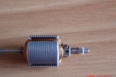
The problem is when the central lock does not work, and the stem can move as usual, by hand. Or central lockingdoes not always work (once). In this case, the central locking motor failed. Disassembled activator motor, where “A” is the collector pole with a winding soldered to it, “B” is the collector poles, and “C” is the collector brushes. 


The central locking motor may not work for a number of reasons:
Car headlights and optics Headlights for cars with delivery in Ukraine. Original and analogues. Address and phone number aksmir.com.ua
Correct installation of the central lock (activator)
Incorrect installation of the activator in the car door increases wear on parts, that leads to broken central lock.
Install activator can be as desired (vertically, horizontally or obliquely), as well as closing can be extension of the stem or vice versa.
It is important that there is enough space for the activator to work, there is enough space for the rod to pass through, as well as a convenient and reliable connection of the rod, and the availability of fastening.
Check the operation of the central lock should be done with the windows down and after installing the door trim.  activator mount should be on as flat a surface as possible. A slight misalignment when fastening on an uneven surface with the force of self-tapping screws can cause difficulty in the operation of the gear shafts. When installing the activator, it is recommended to use washers or bushings to level the surface. If the activator gets into the holes in the metal of the door, then it is necessary to use the plate from the activator kit.
 The design of the VAZ 2110 door implies bending thrust, so it is important to bend the rod correctly. The angle should be clear and preferably minimal. If the angle approaches the arc or the distance of the activator attachment from the rod itself is very large, then instead of the effort of moving the standard rod, we will get an effort to overcome the bend of this arc. It is clearly seen in the second figure, where the activator, pushing the rod up, will apply efforts to the standard rod not up, but to the side.
If the central lock does not work correctly and the activator does not always have enough power to open or close the door, then forces should be directed to find the cause and eliminate the malfunction. However, enthusiasts have found another solution to this problem - finalized the central locking VAZ 2110(installed a second activator). That is, the second activator is additional and helps the work of the first regular activator. The yellow arrow is the direction of movement of the rod of the standard mechanism, and the red arrow is the movement of the additional activator. 

Actually if the activator is correctly installed, no additional activator is required and one activator can perfectly cope with its task.
 An example of incorrect installation of the central lock. The yellow arrow is the movement of the standard thrust, the red arrow is the movement of the activator rod. As a result, the rod force will be applied to the fracture and the steel rod will eventually start to pop out of the rod hole. The error is eliminated by installing plates (green) under the activator (orange). Thus, the activator will be as close as possible to the standard rod and the activator rod bends will be minimal.
Proper fastening of the lock rod  Rod fastening element has a through hole for the activator rod and a split side for attachment to the standard rod. If the fixing screws are loosened, then this element should move freely on the activator rod. We select the place of attachment and fix the screws with due effort. Push the activator rod down by hand, then push the standard rod in the direction corresponding to the closed state of the door lock.
After both rods are retracted, we fix the screw on the activator rod with medium force. Holding the standard rod in place, we extend the activator rod together with the fastening by 2-3 mm and fix the fastening on the regular lock rod with medium force.
Job Check: We check by hand the movement of the activator together with the door lock mechanism, the latch must be closed. We check the opening of the latch in the extreme positions of the activator. We check in what positions the rest of the doors are closed. The main thing is that it should not be one of the extreme positions or close to the extreme position of the additional activator. We check the operation of the window lifter. We apply the door trim for subsequent fastening and the absence of protruding elements. If everything is fine, we tighten the screws for fastening the rods with maximum effort.
We check the operation of the activator by hand again. We check the operation of the activator from the battery. We briefly touch the long wires from the battery to the wires of the activator, change the polarity and the operation of the activator in the other direction.
A number of digressions, amendments and wishes:
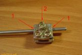 If the fastening screw #2 on the rod loosens, then there may be several options:
The rod slides in the hole and the lock does not move.
The lock either closes or opens. This is because the sharp edges of the element (at points 1) can bite the thrust and, depending on the upper or lower point, it will either only close or, on the contrary, open.
Installation of the activator on cable traction
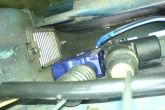
Actually, the installation is similar to that described above, but the attachment to the cables of the lock mechanism is shown in the photo.
Fig2: Mounting the kit on the metal of the door and mounting the cable in the jacket
Fig3: The cable is unjacketed between the fasteners.
Fig4: Connecting the activator rod to the cable. 


This kit is hard to find on sale, so the plate can be cut out of metal yourself, and the spring fasteners can be taken from the Gazelle stove (fastening the cable shirt) of the activator.
Conclusion
Reasons for failure of the central lock many, some of them are related to climatic conditions (cold winters, high humidity, etc.), and some are due to incorrect installation or adjustment of the central lock. In any case, by the symptoms, you can understand where approximately or exactly electrical lock problem.
By the way, do you know how to install additional. central locking button?
Despite the fact that central locks (CL) are now installed almost without exception on all cars, some cars are not equipped with this protection system. Although it is difficult to call it a system, since the only obstacle that the central lock provides for an intruder is the closed car doors. For more information on how to put on a VAZ 2110 car, read this article.
The principle of operation of the central lock
On the VAZ 2110, the central lock is a system designed to open and close vehicle doors. For more convenient control of the central lock on the VAZ 2110, and on other cars, the remote control has long been used. If necessary, the central lock can be configured so that it turns on automatically after a certain period of time. Depending on the system, the key fob can also control the tailgate, engine compartment, and sometimes the central lock even allows you to open and close the windows. In the event of an accident, the central lock can work automatically by opening all the doors of the vehicle.

The VAZ central lock includes sensors in its design - these are door limit switches, solenoids, as well as a control unit. The limit regulator is designed to fix the position of the doors, and data about this, in turn, is transmitted to the VAZ 2110. The purpose of the switches is to fasten the structural elements of the door lock.
The locking of the system itself is carried out using one switch, and the unlocking function is performed by another sensor. The design includes two more switches that ensure the normal operation of the locking mechanism. Another - the fifth switch - is mounted on the lever mechanism of the drive, its purpose is to detect the position of the door. If the car door is open, then the contacts of the elements are closed, respectively, the entire system is deactivated. To perform a particular function, the control unit sends an impulse to certain control devices, thus setting the drive into action.

Possible malfunctions of the locking system
If you need to learn how to find the main control unit with your own hands, then first of all you need to familiarize yourself with the service book - it should indicate where the mechanism is located. As a rule, there is a block under the center console, sometimes it can be hidden in the door itself. It's no secret that any device cannot work forever, and over time, failures may also appear in the operation of the central lock. In practice, the device can often stop functioning due to the fact that the driver, using the remote control, transmits an extended or rapid signal to open or close the doors.
If the central locking stopped working for this reason, then first of all you need to check the activators. When a long signal is given, it leads to heating of the collector of the electric motor of the system, as a result, this may lead to melting of the brush holder. The latter can jam. VAZ 2110 in this case will be to replace this element.
To protect the electrical wiring, a safety device is used, located in the cabin vehicle, right behind the block. If you have a VAZ 2110 central locking diagram, then you can easily find this element. In the event that the central lock is not functioning, you need to check this component. It will also be necessary to repair the central lock if the wiring plug, which is usually located at the driver's feet, is oxidized.
As practice shows, sometimes the cause of the breakdown is the modular block of the central lock. Its diagnostics consists in applying voltage to the connector contact directly from the battery. In gear activators, the gears are made of plastic, respectively, they wear out over time, so they will also need to be changed. But the solenoids are the weakest point of the system - they break most often.
Installation instructions

In your car is carried out in this way:
- First you need to disconnect the battery and dismantle the car door trim and dismantle the power windows. Having done this, you need to choose a place to mount the activator. The installation of this element is carried out in any position, it is important that there is a lot of space for the operation of the device so that the draft can pass freely. It should also be borne in mind that the traction should be connected most conveniently.
- Mount the activator on the most even surface. If you allow even a slight misalignment, which can happen as a result of fixing the device on an uneven surface, this can cause difficulties in the operation of the gear shafts. When mounting the device, it will be necessary to use washers or bushings, this will ensure that the surface is leveled. In the event that the element falls into a hole in the metal of the door, a special plate should be included with the activator, use it.
- Since the design of the “ten” doors is peculiar, the rod itself must be correctly bent before installation. The bend angle itself should be minimal and preferably the clearest. In the event that the angle is close to the arc itself or the distance from the rod to the element lock is too large, problems will arise in the operation of the central lock. The system will not increase the power to move the thrust, but will give this effort to overcome the bend in the arc.
- The field of installation of this element is the laying of wires from each door to the place where the control unit will be installed. The wires must be routed at the bottom of the doors so that they are not affected by power windows and other moving body components. At the junctions, the wires must be well insulated, otherwise moisture can cause the system to close. For laying the wiring between the doors and the body, there are special rubber corrugations - the wires must be passed through them. P When laying the wires in the door, make sure that they will not be broken when closing.
- The next step is to install the block. As a rule, the block is placed either behind the center console or in the car door. It should be borne in mind that the unit must be located in a hard-to-reach place for an attacker, but at the same time this place must be dry and protected from moisture. Therefore, if you decide to put the central locking block on the door, then you should never put it at the bottom, since moisture and dirt usually accumulate here. After some time of operation, these factors will lead to the fact that the unit will not be able to work normally. Also, when installing the unit, pay attention to the fact that power windows should not interfere with its operation, and the unit itself should not interfere with them.
- After installing the unit, the wiring is connected; for this, the VAZ 2110 central lock connection diagram is used, which should come with the system. After connecting, check if the central lock is working properly. If the solenoid does not have enough force to open the rods, you need to find the cause and get rid of the malfunction (the author of the video is the SIMPLE THINGS channel).
Repair features
As a rule, in the event of a central locking malfunction, experienced electricians first of all check the condition of the sensors. If the central lock is connected to the anti-theft system, then it is it that is checked first. As mentioned above, activators fail most often, so they should also be checked.
In the event that a certain door refuses to work, the reason must be hiccupped in it. It can be either the solenoid itself or the wires. During the operation of the car and the frequent opening and closing of doors in the wiring circuit, a break may occur due to bending and mechanical breakdown of the wire itself. If this is the case, then the wire must be replaced or the broken parts reconnected, and then insulated.
This review discusses how to connect an alarm to the central lock of the following cars: VAZ-21099, as well as 2110 and 2115. There are three standard connection schemes: for central locking controlled by negative polarity, positive and variable. But for different cars there are some nuances. Sometimes it is required to add a fuse to the “+12 Volt” wire, sometimes, on the contrary, this is not required. VAZ locks, in turn, belong to the simplest type, to the first. But the standard scheme published on the Internet is not suitable for them.
Features of the central lock VAZ
Everyone knows that in the "Frets" of the models listed here, a central lock is used, controlled by negative polarity. This means literally the following: we apply “0 Volt” to one posting - all the locks are closed. We apply the same voltage to another wire (second) - they unlock. This is how it is done in many European cars. And what is "apply" 0 Volts "? This means connect the wire to ground.
Central lock control unit connector
The central locking control unit has the following wiring:
- Black wire - ground (connected all the time);
- Pink - power supply "+12V" (built-in fuse is used);
- Yellow, red - connected to the actuators in the doors (these wires are not connected to the signaling!);
- Brown, white - control wires, just those that have already been mentioned.
Consider the central locking connection scheme, which is implemented "from the factory":
 Standard wiring diagram for central locking
 At first, we can decide that a triangular connector (marked as "C") is suitable for our purposes, since it contains control contacts. But, pay attention - the standard circuit uses a microswitch located in the driver's door. We will break the two wires coming from this switch, and the relays built into the alarm unit will be connected to the breaks. Other options are excluded.
Let's make friends alarm and central locking
Any modern alarm unit is equipped with two relays connected to the central locking control unit. One relay is opening, the second is locking, and the circuit in the general case looks like this:
 Management of the central locking supply of "mass"
 The green and white cords coming from the signaling unit, in our case, will be required, as indicated in the diagram. However, not only they will be needed. We will include relay contacts in breaks in standard wiring. So, there will be not 2 cords, but 4.
Wiring diagram for central locking VAZ
Look again at the diagram published in the first chapter. We will include the relay in the gap of the white and brown wires coming from the microswitch to the central locking control unit. And it is obvious that it is easier to break these wires near the 8-pin connector. The one shown at the beginning.
To avoid questions, let's show what should be the result:
 Wiring diagram, CZ VAZ
The common contacts are connected to the wires coming out of the mikrik. The white cord continues with the brown wire coming from the door, and so on. Normally closed contacts are also used, along with normally open contacts. These are the features of connecting to the central locking VAZ.
An approximate sequence of actions performed by the installer:
- Make and lay a 4-core cable passing from the signaling unit to the 8-pin connector;
- Connect the cable on the side of the signaling unit (see the last diagram);
- Near the 8-pin connector, break the white and brown wires coming from the microswitch (pins 5 and 7). The main thing is not to confuse them with the wires going to the triangular connector "C";
- Connect to breaks in wires, white and brown. That's all.
We brought this sequence in order to emphasize once again - the relays are switched on between the mikrik and the central locking control unit. No additional devices need to be connected. And as a result, the signaling automation will be able to control the state of the locks.
Remember that installation is performed by removing the negative terminal from the battery.
All wires added to the car must be protected (use heat-resistant tubes or electrical tape). Twisting is not the worst way to connect two wires. But it is even better to use soldering.
It would seem that if a person has experience with electrical equipment, he can do everything according to the instructions given. As a result, if no mistakes are made, you may encounter an interesting phenomenon. Instead of closing, there will be a short-term locking followed by opening. And vice versa. What to do in this case?
Take a look at what exactly may be present in some of the configurations:
 Cheaper - no driver actuator
 The driver's door may be missing actuating mechanism. And then, it is useless to connect the signaling to the BU CZ. There is no actuator, which means there is no one to close or open the door and move the mic lever. Let's say the locks are closed, and then we remove the ground from the brown wire and get the following: the white wire is on the ground, unlocking occurs.
We note the following: installation can only be carried out when you are sure that there is an actuator in the driver's door.
There were configurations where only a microswitch was installed. There is no need for arrogance here - it will be difficult to add an actuator, since standard wiring must go to it. From the factory, as you understand, it may be absent. And what to do then is not clear.
There was one unresolved question - where exactly is the central locking control unit located. In these VAZ models, if there is a central lock, then there is a BU. And it is located under the cover of the torpedo, next to the driver, on the right:
 VAZ-2110, BU TsZ
 We remove the "beard" of the torpedo and look at what is on the top right. On the same plane with the radio connector, two boxes are attached - the one we need, as well as the immobilizer (if any).
We would be cunning if we didn’t say that in reality there is another option for installing the signaling. Normally, only two power cables go to the actuators. Having a power outlet equipped with a fuse, these cables are connected directly to the signaling relay. This option, as you might guess, is not recommended. Imagine what would happen if the alarm went off. The central lock must remain, and in this case it will not be fulfilled. Happy connection!
Installation of the VAZ-2110 lock actuator
Almost set the alarm
There was a problem connecting the central lock.
On the standard block of the central locking VAZ-2110 there are free 6 and 8 contacts. Is it control and what polarity is it controlled by?
don't tell me where it is?
I installed the signaling - I looked for the central locking unit, I covered everything, but I didn’t find it. I got out of the situation by finding the wires in the harness from the central locking. Control - negative polarity (at least for me)
2002-04-29 11:05
Re: Can you tell me where it is?
The central locking unit is located next to the engine control unit, a little higher, closer to the radio. Nearby is also a regular immobilizer.
2002-04-29 12:43
Re: Central lock control VAZ-2110?
In my opinion, you need to connect the alarm to the brown and white wires. Which one is responsible for opening, and which one is for closing, I don’t remember. CZ refers to a three-wire system with negative polarity.
2002-04-29 12:40
Listen here
The central locking unit is located under the center console. It is better to get to it by unscrewing the left (driver's) shield at the driver's feet. But it's still not visible (I couldn't). And only by touch, when I saw a suitable wiring harness, I reached out to the block with my hand and with great difficulty disconnected the connector from it (Soviet connectors are the most difficult to disconnect - I pulled and shook for about ten minutes)
I confidently advise you to entrust the control of the locks not to this block, but to the signaling itself. The fact is that there have been cases when this block is buggy and does not turn off the mechanisms in the doors - as a result, all 4 locks are burning together. (When I recently passed TO1, I myself witnessed how all 4 locks and this block were changed to a peasant on a 10-ke. According to the peasant, they started doing it at 11 o'clock, I left with TO at 18 o'clock, and the end of the work was not visible for the peasant - the electricians could not share the blame with the signallers). So pull out this connector and connect the signaling wires to it. And everything will be OK.
Best regards, Eugene
The central locking VAZ-2110 for the owner of this car is considered a fairly safe device. Keeping pace with progress, a person strives to be in time everywhere. This type of transport, like a car, has long become not a luxury, but a means of transportation. According to statistics, every second person drives a car.
1. Mounting block. 2. Fuse for 8 A. 3. Control unit. 4. Motor reducer for blocking the lock of the right front door. 5. Motor reducer for blocking the lock of the right rear door. 6. Motor reducer for blocking the lock of the left rear door. 7. Motor reducer for blocking the lock of the left front door with contact group. A - to power supplies; B - conditional numbering of plugs in the block of the control unit; C - conditional numbering of plugs in the blocks of gear motors for blocking locks.
Today, the products of the domestic auto industry are not in great demand, as foreign cars dominate the market. But not everyone can afford a foreign car. Therefore, people buy cheaper vehicles of domestic production. One of these cars is the VAZ 2110, which was distinguished by its stable performance, low cost of repair and simple operation.
The principle of operation of the central lock
The central lock is a system that, with a specific command, performs the function of opening or closing an object. For convenience, this operation is performed remotely. Some motorists choose the function of closing all doors after a certain period of time. It is very convenient for those cases when the driver does not have time or forgets to close the car door.
As a rule, with the help of a remote control, you can control both the trunk and the hood, close and open the windows. The most common way to control a remote control is to press one button, after which all the locks on the car work. If the remote control does not work for some reason, then you need to insert the key into the door lock and turn it clockwise.
If an accident occurs, the car's security system is activated automatically, all locks open. At the heart of the central locking mechanism there are incoming sensors located in the structure itself. These are microswitches and door switches (limit switches), actuators and a control unit.
The limit switch must hold the position of the door, and this information must be transmitted to the control unit. The switches fix the structural part of the door lock. The cam device is equipped with the front door of the car. To fix the cam, the front doors are equipped with microswitches: there are two parts for each mechanism.
Locking the lock forms one switch, and unlocking the second. There are two more microswitches used by the central locking mechanism. A fifth switch is installed on the lever device in the lock drive. It serves to determine the position of the door: when the door is open, the switch contacts close, the central locking system is deactivated.
The electronic mechanism (unit) receives the signal from the microswitches and sends the information to the central control. In order to open an object, the central device sends a signal to certain control units, thereby activating the mechanisms in the locks.
Possible problems with the locking system
As we know, any equipment sooner or later fails. And the central lock on the VAZ 2110 is no exception. There are a number of problems that manifest themselves in the operation of this system. Many motorists inadvertently destroy the security system of the car. The driver must not give a long or rapid impulse to a request to open or close the door.
Scheme of the central lock on the VAZ 2110
This action can disable the activator, with which the locking device works. When a long pulse is applied, the collector of the activator electric motor is very hot. In this regard, the brush holder begins to melt, and it may jam. After that, the activator will need to be replaced.
Protects the circuit of the central locking fuse. It is from him that they begin to search for a malfunction in the operation of the entire circuit. It is located inside the car, behind the fuse box. According to the scheme, it stands on the break of the pink wire (in isolation). Under the driver's mat there is a wire with a plug connector that accumulates moisture and oxidizes. Lost power to the activator.
The modular block of the central lock can break. You should check its performance by applying voltage from the battery to the contact of the module connector. The gears of the gear activator are made of plastic. Such parts are subject to wear, and this is a mechanical failure.
But the solenoid is considered the weakest point of the central lock, most often it is he who fails. The electromagnet is controlled via a switch. When opening and closing doors, the resource of solenoids is designed for approximately 10 thousand operations. After this number of switchings, malfunctions begin. The repair is simple: you need to replace the solenoid itself.