Sent by:
Part 1. The manufacture of a classic low-speed generator based on permanent magnets about 35W at 200 rpm and about 160W at 400 rpm.
1. Introduction
This is a manual for making a permanent magnet generator (PMG) that produces alternating current. It does not generate an "industrial" voltage of 220V, but a low alternating voltage in three phases, which is then rectified and supplied to the output in the form direct current with parameters suitable for charging 12V batteries.
Such generators are widely used in home-made mini-hydroelectric power plants, windmills and other do-it-yourself power plants. Description developed by Dr. Smale Hennas, published on the website of the famous Scottish DIYer and author of numerous manuals Hugh Pigot.

This permanent magnet generator consists of the following components:
1. Steel axles and trunnions (shafts and spines)
2. Stator containing coils of wire (Stator)
3. Two magnetic rotors (magnet rotor)
4. Rectifier
The stator contains six coils of copper wire filled with epoxy resin. The stator housing is fixed with trunnions and does not rotate. The wires from the coils are connected to a rectifier which produces direct current to charge the 12V batteries. The rectifier is attached to aluminum radiator so as not to overheat.
The magnetic rotors are fixed on a composite structure rotating on the axis. The rear rotor is installed behind the stator and is closed by it. The front rotor is on the outside and is attached to the rear rotor by long spokes running through the center hole of the stator. In the case of using a permanent magnet generator with a windmill, the windmill blades will be mounted on the same spokes. They will rotate the rotors, and thus move the magnets along the coils. The alternating magnetic field of the rotors generates current in the coils.
This permanent magnet generator is designed for use with a small wind turbine. In order to make the wind generator itself, you need the following nodes:
Mast: steel tube fixed with cables (Tower)
"Rotating head", which is mounted on the top of the mast
Tail, for turning the windmill in the wind (tail)
Set of blades (blades)

The permanent magnet generator operates at low speed. The graph below shows the generator power when charging a 12V battery. At 420 rpm it produces 180 watts = 15A x 12V
At higher speeds, the generator produces more power. But more current heats up the coils and efficiency. falls. To use the alternator for high speeds, it is better to wind the coils with a different wire, thicker and make fewer turns in the coil. But at the same time, at low speeds, the generator will work poorly.
In order to use this generator at high and low speed, you can change the way the coils are connected: switch from a star to a triangle and vice versa.
The graph shows the dependence of the output power on the speed for different types of connection. "Star" starts to work at low speed (170 rpm). "Triangle" produces more power, but only at high speeds. A star is good with a small wind, a triangle with a large one.

If you increase the size of the permanent magnet generator, then at the same speeds it can produce more power.
Attention
When manufacturing a permanent magnet generator, pay special attention to the fastening of the magnets - under no circumstances should they be separated from the seat! The dangling magnet begins to tear apart the stator housing and irreversibly damage the generator.
Strictly follow the instructions for casting the rotor - by no means limit yourself to simply gluing magnets to steel disks.
When assembling, do not hit the rotor with a hammer
Leave at least 1mm clearance between rotors and stator (larger clearance for heavy duty applications)
Do not operate the permanent magnet generator at speeds above 800 rpm. (When the windmill turns at this speed, gyroscopic forces arise in it, which can bend the axles and cause the magnets to touch the rotor)
Do not attach the blades directly to the outer rotor, attach only to the spokes.
When attaching the blades to the spokes, hold the generator so that its axis of rotation is vertical, never horizontal.


Rotor, bearing assembly, profile with axle
Materials for casting molds and tooling.- Floorboards and wood glue
- Sandpaper, wax polishing (if any - polyurethane varnish + liquid for its removal)
- Paint brushes, sponge for cleaning them
- Plywood 13 mm for tooling and molds
- Steel rod or tube for winder
- Pieces of thick metal sheet
Tools
- Goggles, mask, gloves
- Workbench with vise
- Welding machine
- angle grinder
- hacksaw, hammer, punch, chisel
- tape measure, compasses, protractor
- wrenches: 8, 10, 13, 17, 19 mm, 2 of each type
- knob and tap M10 for holes in the magnetic rotor
- copper wire for magnet positioning
- vertical drilling machine
- drills 6, 8, 10, 12 mm
- drill bit for making holes 25 mm, 65 mm
- wood lathe
- lathe cutter
- jigsaw for wood
- scales for weighing epoxy. Catalyst sprayer, plastic trays, scissors
- soldering iron, solder with flux, wire cutters, sharp knife
This section describes the manufacture of special devices (rigging) and molds for casting. There are many ways to manufacture such devices, one of them is described here. Casting molds and tooling for permanent magnet generator can be reused.

3.1 Winder
The generator stator contains 6 coils of 100 turns of copper wire.

Coils are made by winding on a plywood template. The template is mounted on the end of the handle, between the plywood cheeks.
Making a pen

Cut off a piece of steel plate 60x30x6 mm (give or take) and securely attach it (or weld) to the end of the handle, as shown below.
We drill 2 holes with a diameter of 6mm at a distance of 40mm from each other

Cut out 3 pieces of 13mm plywood as shown below.

The template measures 50 x 50mm and is 13mm thick. The edges are rounded. Two cheeks - 125 x 125 mm, with cutouts 20 mm deep at the top and bottom. Cutouts are needed in order to fix the coil with electrical tape after winding.
We assemble all the parts as shown below and drill through holes for bolts, diameter 6mm, at a distance of 40mm. It is best to use a vertical drilling machine.

Insert two bolts through the holes in the steel plate and assemble the whole structure, a template between the cheeks. It is best to use wing nuts.

Mounting hole template.
The magnetic rotors are mounted on a bearing hub. The assembly has a flange with holes. For example, it can be 4 holes located on a circle with a diameter of 102 mm (in English there is a special term pitch circle diameter, PCD). Or you can design a different number of holes, depending on the bearing assembly. Next we look at PCD 102mm.

The PCD template will be used to drill holes in the rotor and also to balance the rotor. Holes must be marked and drilled with the utmost precision.
a) cut a 125 x 125 mm square steel plate
b) draw diagonals and punch the center
c) expand the compass to a radius of 51 mm, draw a circle
d) circle diameter is PCD
e) mark 2 points of intersection of the circle and one of the diagonals
f) retract the compass by 72 mm (figure is correct for PCD 102 mm). Mark two points on the circle exactly at a distance of 72 mm from the previous two.
g) Drill 4 holes 72mm apart, use a small diameter drill first.

Template for positioning magnets

a) Mark the center of the plywood blank
b) Draw from the marked point 3 circles with a diameter of 50mm, 102mm and 200m
c) Draw 2 parallel lines as tangents to the 50mm circle (pictured above)
d) Draw 3 more pairs of parallel lines at 45 and 90 degrees to the first pair.
e) Using the lines, mark the places for the magnets, and cut out the template along the heavy line (picture above)
f) Draw a line between the centers of two opposite magnets
g) Lay the steel PCD mounting hole template on the 102mm circle, align it with the line between the centers of the magnets, and drill holes through the holes in the steel template.
3.3 Molds and tooling: Making casting molds
Let's start making molds for casting the rotor and stator. They can be made from wood or aluminium. Another way is to sculpt molds out of clay and level them on a potter's wheel like a pot. The mold surface will be the outer surface of the stator or rotor. Then fiberglass inserts will be added inside the mold. The surface of the mold should be as smooth as possible.
Forms must be strong. The stator or rotor is not easy to knock out of shape after curing, a couple of hits with a mallet may be needed.
Cut out some discs from the floorboard (picture below), about 500mm in diameter.

In all discs except one, cut round holes, 360mm in diameter, to get the rings.

On the remaining disk, draw a circle 360 mm in diameter
Drill a 12mm hole in the center of the disc
Glue the rings to the disk to make a 60mm high stack. Smear more glue inside.
Cut a disc out of 15mm plywood with a diameter of 140mm, drill a 12mm hole in its center
Insert a 12mm bolt through both holes and glue the small disk to the center of the large disk. Smear more glue around the edges of the disc

Attach the structure to another homemade disc, or to a lathe disc, or to a wheel. In general, you need what is called a faceplate (holder) in the figure below.
Turning the holder, draw a circle in its center with a pencil.
Drill a 12mm hole in this center. The drill must be strictly parallel to the axis.
Screw the glued discs (hereinafter referred to as the blank) to the holder with a 12mm bolt. Secure with additional 4 screws.
Check workpiece rotation. To do this, you need to hold the pencil near the surface when the workpiece rotates. If the pencil leaves a mark, then there is a bulge on the surface in this place. Loosen the screws and insert pieces of paper between the holder and the workpiece on the opposite surface of the workpiece against the pencil marks. Tighten the screws and try again

Now you can process the workpiece with a cutter.

Cut a flat surface on the inside of the workpiece.
Make a 7 degree chamfer on the inner surface
The overall diameter of the inside should be 380mm
Flat part diameter 360mm (see picture below)
Internal corners are rounded, not sharp

Grind the inner disc to a diameter of 130mm. The corners are also rounded (picture below)

Check that the coil fits into its place freely - if not, then either slightly bore the inner surface, or reduce the diameter of the inner disk.
Remove the workpiece from the lathe.

Drill 4 holes in the central part (they are needed to separate the outer and inner stator molds, the inner mold is described in the next section). Hammer small pieces of plywood into the back of the holes to make a "stop".
3.3.2 Internal mold for the stator.Cut discs with a diameter of 370 mm
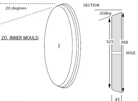
Drill a 12mm hole in the center of each
Glue them in a stack (fig. above), fasten with a 12 mm bolt
The stack must be at least 45 mm thick, preferably 50 mm
Run a 20-degree cutter along the edge, cut the corner so that the diameter decreases from 368 mm to 325 mm

Check that the outer mold sits on the inner mold with a 6mm gap around the edge. Then remove the inner mold from the machine.
Mark two lines on the larger surface of the mold, 340mm apart.
Cut the chamfers as shown below

Chamfers will make it possible to make influxes of filling material in these places and thereby strengthen the stator attachment points.
3.3.3 casting mold for the rotor.The generator requires 2 magnetic rotors. They need one casting mold, but it is better to have two to speed up the process.
The outer shape for the rotor (fig. below) is similar to the outer shape for the stator, but simpler:

Using the mounting hole template (discussed above), drill 4 holes to later mount the magnetic rotors.
Casting magnetic rotor also requires an internal casting mold (fig. below), with the same marking of the fixing holes.

All forms must be sanded down to obtain a very smooth surface, which must be finished with a waxed polyurethane sponge grout.
It is not necessary to paint the molds: when heated, the paint will crack and ruin the surface of the casting.

3.3.4 Stator templates
Template for pins.
When pouring into the stator, 4 supporting 8 mm pins must be sealed. So that they do not warp while the epoch is drying, they are fixed in place using a template that we will now make. The template is made from a wooden block 380 x 50 x 25 mm. The dimensions must be precisely maintained, otherwise the pins will then not coincide with the mounting pins.
a) mark the center of the bar on the largest edge (fig. below)
b) draw with a compass two arcs with a radius of 178 mm
c) mark 2 points on each arc, 30 mm apart and 10 mm from the edge.
d) Drill 4 holes 8mm, best with a drill press
e) Deburr the exit holes carefully to avoid leaving a mark on the casting.

paper template
For the manufacture of the stator, the so-called powder glass mat (glass material with a powder binder) is used. To cut out the stator components from it, make paper templates. They can be circled with a felt-tip pen and cut out the resulting figure from glass mat.
Wrap the shape with a sheet of paper and mark the edge.

To be continued.
Content:In modern conditions, constant attempts are being made to improve electromechanical devices, reduce their weight and overall dimensions. One of these options is a permanent magnet generator, which is a fairly simple design with a high efficiency. The main function of these elements is to create a rotating magnetic field.
Types and properties of permanent magnets
Permanent magnets made from traditional materials have been known for a long time. For the first time in industry, an alloy of aluminum, nickel and cobalt (alnico) began to be used. This made it possible to use permanent magnets in generators, motors and other types of electrical equipment. Ferrite magnets are especially widespread.
Subsequently, samarium-cobalt hard magnetic materials were created, the energy of which has a high density. They were followed by the discovery of magnets based on rare earth elements - boron, iron and neodymium. The density of their magnetic energy is much higher than that of the samarium-cobalt alloy at a significantly lower cost. Both types of artificial materials successfully replace electromagnets and are used in specific areas. Neodymium elements are among the materials of a new generation and are considered the most economical.
The principle of operation of devices
The main design problem was considered to be the return of rotating parts to their original position without significant loss of torque. This problem was solved by using a copper conductor, through which an electric current was passed, causing attraction. When the current was turned off, the action of attraction ceased. Thus, in devices of this type, periodic on-off was used.

The increased current creates an increased attractive force, and that, in turn, is involved in the generation of current passing through the copper conductor. As a result of cyclic actions, the device, in addition to performing mechanical work, begins to produce electric current, that is, to perform the functions of a generator.
Permanent magnets in generator designs
In the designs of modern devices, in addition to permanent magnets, electromagnets with a coil are used. This combined excitation function allows you to obtain the necessary voltage and speed control characteristics at a reduced excitation power. In addition, the size of the entire magnetic system is reduced, which makes such devices much cheaper compared to classical designs of electrical machines.

The power of devices that use these elements can be only a few kilovolt-amperes. Currently, permanent magnets are being developed with the best performance, providing a gradual increase in power. Such synchronous machines are used not only as generators, but also as motors for various purposes. They are widely used in mining and metallurgical industries, thermal power plants and other fields. This is due to the possibility of operation of synchronous motors with different reactive powers. They themselves work at a precise and constant speed.
Stations and substations operate together with special synchronous generators, which are in the mode idle move provide only reactive power. In turn, it ensures the operation of asynchronous motors.
A permanent magnet generator works on the principle of interaction between the magnetic fields of a moving rotor and a stationary stator. Not fully understood properties of these elements allow us to work on the invention of other electrical devices, up to the creation of fuel-free.
The present invention relates to the field of electrical engineering, namely to brushless electric machines, in particular DC generators, and can be used in any field of science and technology that requires autonomous power sources. The technical result - the creation of a compact high-performance electric generator, which allows, while maintaining a relatively simple and reliable design, to widely vary the output parameters electric current depending on operating conditions. The essence of the invention lies in the fact that a brushless synchronous generator with permanent magnets consists of one or more sections, each of which includes a rotor with a circular magnetic circuit, on which an even number of permanent magnets are fixed with the same pitch, a stator carrying an even number of horseshoe-shaped electromagnets arranged in pairs opposite each other and having two coils with a series of opposite windings, a device for rectifying electric current. Permanent magnets are fixed on the magnetic core in such a way that they form two parallel rows of poles with longitudinal and transverse alternating polarity. Electromagnets are oriented across said rows of poles so that each of the electromagnet coils is located above one of the parallel rows of rotor poles. The number of poles in one row, equal to n, satisfies the relation: n=10+4k, where k is an integer that takes the values 0, 1, 2, 3, etc. The number of electromagnets in the generator usually does not exceed the number (n-2). 12 w.p. f-ly, 9 ill.
Drawings to the RF patent 2303849


The present invention relates to brushless electric machines, in particular DC generators, and can be used in any field of science and technology that requires autonomous power sources.
Synchronous machines alternating current received the widest distribution both in the sphere of production and in the sphere of consumption of electric energy. All synchronous machines have the property of reversibility, that is, each of them can operate both in generator mode and in motor mode.
A synchronous generator contains a stator, usually a hollow laminated cylinder with longitudinal grooves on the inner surface, in which the stator winding is located, and a rotor, which is permanent magnets of alternating polarity, located on a shaft that can be driven in one way or another. In high-power industrial generators, an excitation winding located on the rotor is used to obtain an exciting magnetic field. In synchronous generators of relatively low power, permanent magnets are used located on the rotor.
At a constant speed, the shape of the EMF curve generated by the generator is determined only by the law of distribution of magnetic induction in the gap between the rotor and the stator. Therefore, to obtain a voltage at the output of a generator of a certain shape and to effectively convert mechanical energy into electrical energy, different rotor and stator geometries are used, and the optimal number of permanent magnetic poles and the number of turns of the stator winding are selected (US 5117142, US 5537025, DE 19802784, EP 0926806, WO 02/003527, US 2002153793, US 2004021390, US 2004212273, US 2004155537). The listed parameters are not universal, but are selected depending on the operating conditions, which often leads to a deterioration in other characteristics of the electric generator. In addition, the complex shape of the rotor or stator complicates the manufacture and assembly of the generator and, as a result, increases the cost of the product. The rotor of a synchronous magnetoelectric generator can have a different shape, for example, at low power, the rotor is usually made in the form of an "asterisk", at medium power - with claw-shaped poles and cylindrical permanent magnets. The claw-pole rotor makes it possible to obtain a generator with pole dissipation, which limits the surge current in the event of a sudden short circuit of the generator.
In a generator with permanent magnets, it is difficult to stabilize the voltage when the load changes (because there is no magnetic feedback, as, for example, in generators with an excitation winding). To stabilize the output voltage and rectify the current, various electrical circuits are used (GB 1146033).
The present invention is directed to the creation of a compact high-efficiency electric generator, which allows, while maintaining a relatively simple and reliable design, to widely vary the output parameters of the electric current depending on operating conditions.
The electric generator made in accordance with the present invention is a brushless permanent magnet synchronous generator. It consists of one or more sections, each of which includes:
A rotor with a circular magnetic circuit, on which an even number of permanent magnets are fixed with the same pitch,
A stator carrying an even number of horseshoe-shaped (U-shaped) electromagnets arranged in pairs opposite each other and having two coils each with a sequentially opposite winding direction,
A device for rectifying electric current.
Permanent magnets are fixed on the magnetic core in such a way that they form two parallel rows of poles with longitudinal and transverse alternating polarity. Electromagnets are oriented across said rows of poles so that each of the electromagnet coils is located above one of the parallel rows of rotor poles. The number of poles in one row, equal to n, satisfies the relation: n=10+4k, where k is an integer that takes the values 0, 1, 2, 3, etc. The number of electromagnets in the generator usually does not exceed the number n-2.
The device for rectifying the current is usually one of the standard rectifier circuits made on diodes: full-wave with a midpoint or bridge, connected to the windings of each electromagnet. If necessary, a different rectification circuit can also be used.
Depending on the features of the operation of the electric generator, the rotor can be located both on the outside of the stator and inside the stator.
The electric generator made in accordance with the present invention may include several identical sections. The number of such sections depends on the power of the mechanical energy source (drive motor) and the required parameters of the generator. Preferably, the sections are out of phase with each other. This can be achieved, for example, by initially shifting the rotor in adjacent sections by an angle α ranging from 0° to 360°/n; or angular shift of the stator electromagnets in adjacent sections relative to each other. Preferably, the generator also includes a voltage regulator unit.
The essence of the invention is illustrated by the following drawings:
Figure 1(a) and (b) shows a diagram of an electric generator made in accordance with the present invention, in which the rotor is located inside the stator;
figure 2 shows the image of one section of the generator;
figure 3 shows the principal circuit diagram an electric generator with a full-wave mid-point rectification circuit;
figure 4 shows a circuit diagram of an electric generator with one of the bridge rectification circuits;
Fig. 5 is a schematic diagram of an electric generator with another rectification bridge circuit;
Fig. 6 is a schematic diagram of an electric generator with another rectifier bridge circuit;
Fig. 7 is a schematic diagram of an electric generator with another rectification bridge circuit;
Fig.8 shows a diagram of an electric generator with an external rotor;
Fig. 9 is an image of a multi-sectional generator made in accordance with the present invention.
Figure 1(a) and (b) shows the generator, made in accordance with the present invention, which includes a housing 1; rotor 2 with a circular magnetic circuit 3, on which an even number of permanent magnets 4 is fixed with the same pitch; a stator 5 carrying an even number of horseshoe-shaped electromagnets 6 arranged in pairs opposite each other, and a means for rectifying the current (not shown).
The body 1 of the generator is usually cast from an aluminum alloy or cast iron, or made welded. Installation of the electric generator at the place of its installation is carried out by means of paws 7 or by means of a flange. The stator 5 has a cylindrical inner surface, on which identical electromagnets 6 are mounted with the same pitch. In this case, ten. Each of these electromagnets has two coils 8 with windings in series in the opposite direction, located on a U-shaped core 9. The core package 9 is assembled from chopped electrical steel plates with glue or riveted. The conclusions of the windings of electromagnets through one of the rectifier circuits (not shown) are connected to the output of the generator.
The rotor 3 is separated from the stator by an air gap and carries an even number of permanent magnets 4 arranged in such a way that two parallel rows of poles are formed, equidistant from the generator axis and alternating in polarity in the longitudinal and transverse directions (Figure 2). The number of poles in one row satisfies the relation: n=10+4k, where k is an integer that takes the values 0, 1, 2, 3, etc. In this case (Figure 1) n=14 (k=1) and, accordingly, the total number of permanent magnetic poles is 28. When the generator rotates, each of the electromagnet coils passes over the corresponding row of alternating poles. Permanent magnets and electromagnet cores are shaped to minimize losses and to achieve uniformity (as far as possible) of the magnetic field in the air gap during operation of the generator.
The principle of operation of the electric generator, made in accordance with the present invention, is similar to the principle of operation of a traditional synchronous generator. The rotor shaft is mechanically connected to the drive motor (mechanical energy source). Under the action of the torque of the drive motor, the generator rotor rotates at a certain frequency. In this case, in the winding of the coils of electromagnets, in accordance with the phenomenon of electromagnetic induction, an EMF is induced. Since the coils of an individual electromagnet have a different winding direction and are at any time in the zone of action of different magnetic poles, the induced EMF in each of the windings is added up.
During the rotation of the rotor, the magnetic field of the permanent magnet rotates with a certain frequency, therefore, each of the windings of the electromagnets alternately finds itself in the zone of the north (N) magnetic pole, then in the zone of the south (S) magnetic pole. In this case, the change of poles is accompanied by a change in the direction of the EMF in the windings of electromagnets.
The windings of each electromagnet are connected to a current rectifier, which is usually one of the standard rectifier circuits made with diodes: full-wave with a midpoint or one of the bridge circuits.
Figure 3 shows a circuit diagram of a full-wave rectifier with a midpoint, for an electric generator with three pairs of electromagnets 10. In Figure 3, the electromagnets are numbered from I to VI. One of the outputs of the winding of each electromagnet and the opposite output of the winding of the opposite electromagnet are connected to one output 12 of the generator; other conclusions of the windings of the named electromagnets are connected through diodes 11 to another output 13 of the generator (with this inclusion of diodes, output 12 will be negative, and output 13 will be positive). That is, if for electromagnet I the beginning of the winding (B) is connected to the negative bus, then for the opposite electromagnet IV, the end of the winding (E) is connected to the negative bus. The same is true for other electromagnets.
Figures 4-7 show various rectification bridge circuits. The connection of bridges that rectify the current from each of the electromagnets can be parallel, series or mixed. In general, various circuits are used to redistribute the output current and potential characteristics of the generator. The same electric generator, depending on the operating modes, may have one or another rectification circuit. Preferably, the generator contains an additional switch that allows you to select the desired mode of operation (bridge connection scheme).
Figure 4 shows a circuit diagram of an electric generator with one of the bridge rectification circuits. Each of the electromagnets I-VI is connected to a separate bridge 15, which in turn are connected in parallel. Common tires are connected respectively to the negative output 12 of the generator or to the positive 13.
Figure 5 shows an electrical circuit with a serial connection of all bridges.
Figure 6 shows an electrical circuit with a mixed connection. Bridges rectifying current from electromagnets: I and II; III and IV; V and VI are connected in pairs in series. And the pairs, in turn, are connected in parallel through common buses.
Figure 7 shows a circuit diagram of an electric generator, in which a separate bridge rectifies the current from a pair of diametrically opposed electromagnets. For each pair of diametrically opposed electromagnets, the like terminals (in this case "B") are electrically connected to each other, and the remaining terminals are connected to a rectifying bridge 15. The total number of bridges is m/2. Between themselves, the bridges can be connected in parallel and/or in series. Figure 7 shows a parallel connection of bridges.
Depending on the features of the operation of the electric generator, the rotor can be located both on the outside of the stator and inside the stator. Figure 8 shows a diagram of an electric generator with an external rotor (10 electromagnets; 36=18+18 permanent magnets (k=2)). The design and principle of operation of such an electric generator are similar to those described above.
The electric generator, made in accordance with the present invention, may include several sections A, B and C (Fig.9). The number of such sections depends on the power of the mechanical energy source (drive motor) and the required parameters of the generator. Each of the sections corresponds to one of the designs described above. The power generator may include both identical sections and sections that differ from each other in the number of permanent magnets and/or electromagnets or in the rectification circuit.
Preferably, identical sections are out of phase with each other. This can be achieved, for example, by the initial shift of the rotor in adjacent sections and the angular shift of the stator electromagnets in adjacent sections relative to each other.
Implementation examples:
Example 1. In accordance with the present invention, an electric generator was manufactured to power electrical appliances with a voltage of up to 36 V. The electric generator is made with a rotating external rotor, on which 36 permanent magnets are placed (18 in each row, k=2) made of Fe-Nd alloy -IN. The stator carries 8 pairs of electromagnets, each of which has two coils containing 100 turns of PETV wire with a diameter of 0.9 mm. The switching circuit is a bridge, with the connection of the same conclusions of diametrically opposite electromagnets (Fig.7).
outer diameter - 167 mm;
output voltage - 36 V;
maximum current - 43 A;
power - 1.5 kW.
Example 2 In accordance with the present invention, an electric generator was made for recharging power supplies (a pair of 24 V batteries) for urban electric vehicles. The electric generator is made with a rotating internal rotor, on which 28 permanent magnets (14 in each row, k=1) are placed, made of Fe-Nd-B alloy. The stator carries 6 pairs of electromagnets, each of which has two coils containing 150 turns each, wound with PETV wire with a diameter of 1.0 mm. The switching circuit is full-wave with a midpoint (Figure 3).
The power generator has the following parameters:
outer diameter - 177 mm;
output voltage - 31 V (for charging 24 V battery pack);
maximum current - 35A,
maximum power - 1.1 kW.
Additionally, the generator contains an automatic voltage regulator for 29.2 V.
CLAIM
1. An electric generator containing at least one circular section, including a rotor with a circular magnetic circuit, on which an even number of permanent magnets are fixed with the same pitch, forming two parallel rows of poles with longitudinal and transverse alternating polarity, a stator carrying an even number of horseshoe-shaped electromagnets , arranged in pairs opposite each other, a device for rectifying electric current, where each of the electromagnets has two coils with a series of opposite windings, while each of the coils of the electromagnets is located above one of the parallel rows of rotor poles and the number of poles in one row equal to n satisfies ratio
n=10+4k, where k is an integer that takes the values 0, 1, 2, 3, etc.
2. Electric generator according to claim 1, characterized in that the number of stator electromagnets m satisfies the ratio m n-2.
3. Electric generator according to claim 1, characterized in that the device for rectifying electric current contains diodes connected to at least one of the outputs of the windings of the electromagnets.
4. Electric generator according to claim 3, characterized in that the diodes are connected in a full-wave circuit with a midpoint.
5. Electric generator according to claim 3, characterized in that the diodes are connected in a bridge circuit.
6. Electric generator according to claim 5, characterized in that the number of bridges is equal to m, and they are connected to each other in series, or in parallel, or in series-parallel.
7. Electric generator according to claim 5, characterized in that the number of bridges is equal to m / 2 and one of the outputs of the same name of each pair of diametrically opposite electromagnets are connected to each other, and the others are connected to one bridge.
8. Electric generator according to any one of claims 1 to 7, characterized in that the rotor is located on the outside of the stator.
9. Electric generator according to any one of claims 1 to 7, characterized in that the rotor is located inside the stator.
10. Electric generator according to claim 1, characterized in that it contains at least two identical sections.
11. Electric generator according to claim 10, characterized in that at least two sections are shifted in phase relative to each other.
12. Electric generator according to claim 1, characterized in that it contains at least two sections that differ in the number of electromagnets.
13. Electric generator according to claim 1, characterized in that it additionally contains a voltage regulator unit.
The fact that a neodymium magnet generator, such as a wind generator, is useful is no longer in doubt. Even if all the appliances in the house cannot be provided with energy in this way, after all, with prolonged use, it will show itself from the winning side. Making the device with your own hands will make operation even more economical and more enjoyable.
Characteristics of neodymium magnets
But first, let's find out what magnets are. They appeared not so long ago. It has been possible to buy magnets in the store since the nineties of the last century. They are made of neodymium, boron and iron. The main element, of course, is neodymium. This is a metal of the lanthanide group, with the help of which magnets acquire a huge adhesive force. If you take two large pieces and pull them together, then it will be almost impossible to disengage them.
On sale basically, of course, there are miniature species. In any gift shop you can find balls (or other shapes) made of this metal. The high price of neodymium magnets is explained by the complexity of the extraction of raw materials and the technology of its production. If a ball with a diameter of 3-5 millimeters will cost only a few rubles, then for a magnet with a diameter of 20 millimeters or more you will have to pay 500 rubles or more.
Neodymium magnets are produced in special furnaces, where the process takes place without access to oxygen, in a vacuum or an atmosphere with an inert gas. The most common are magnets with axial magnetization, in which the field vector is directed along one of the planes where the thickness is measured.
The characteristics of neodymium magnets are very valuable, but they can easily be damaged beyond repair. So, a strong blow can deprive them of all properties. Therefore, you should try to avoid falling. Also at different types there is a temperature limit, which varies from eighty to two hundred and fifty degrees. At temperatures above the limit, the magnet loses its properties.
Proper and careful use is the key to maintaining quality for thirty years or more. Natural demagnetization is only one percent per year.
Application of neodymium magnets
They are often used in experiments in the field of physics and electrical engineering. But in practice, these magnets have already found wide application, for example, in industry. Often they can be found in the composition of souvenirs.
The high degree of grip makes them very useful when searching for underground metal objects. Therefore, many search engines use equipment using neodymium magnets to find equipment left over from wartime.
If the old acoustic speakers barely work, then sometimes it is worth attaching neodymium magnets to the ferrite magnets, and the equipment will sound great again.
So on the engine or generator, you can try to replace the old magnets. Then there is a chance that the technique will work much better. Consumption will also go down.
Mankind has been looking for a long time On neodymium magnets, as some believe, the technology may well take on a real shape.
Ready-made vertically oriented wind turbine
There has been renewed interest in wind turbines, especially in recent years. There are new models that are more convenient and practical.
Until recently, horizontal wind turbines with three blades were mainly used. And vertical views did not spread due to the heavy load on the bearings of the wind wheel, as a result of which increased friction arose, absorbing energy.
But thanks to the use of the principles of magnetic levitation, the wind generator on neodymium magnets began to be used precisely vertically oriented, with a pronounced free inertial rotation. At present, it has proven to be more effective than horizontal.
Easy start is achieved thanks to the principle of magnetic levitation. And thanks to the multi-pole, which gives the rated voltage at low speeds, it is possible to completely abandon the gearboxes.
Some devices are able to start working when the wind speed is only one and a half centimeters per second, and when it reaches only three or four meters per second, it may already be equal to the generated power of the device.
Application area
Thus, the wind generator, depending on its power, is able to provide energy to various structures.
City apartments.
Private houses, dachas, shops, car washes.
Kindergartens, hospitals, ports and other city institutions.
Advantages
Devices are purchased ready-made or made independently. Having bought a wind generator, it remains only to install it. All adjustments and alignments have already been completed, tests have been carried out under various climatic conditions.
Neodymium magnets, which are used instead of the gearbox and bearings, allow you to achieve the following results:
friction is reduced, and the service life of all parts is increased;
vibration and noise of the device disappears during operation;
the cost is reduced;
saves electricity;
eliminates the need for regular maintenance.
The wind generator can be purchased with a built-in inverter that charges the battery, as well as with a controller.

The most common models
The generator on neodymium magnets can be made on a single or double mount. In addition to the main neodymium magnets, additional ferrite magnets can be provided in the design. The height of the wing is made different, mainly from one to three meters.
More powerful models have a double mount. They also install additional generators on ferrite magnets and have different wing heights and diameters.
Homemade designs

Considering that not everyone can afford to buy a wind-powered neodymium magnet generator, they often decide to build a structure with their own hands. Consider various options for devices that you can easily make yourself.
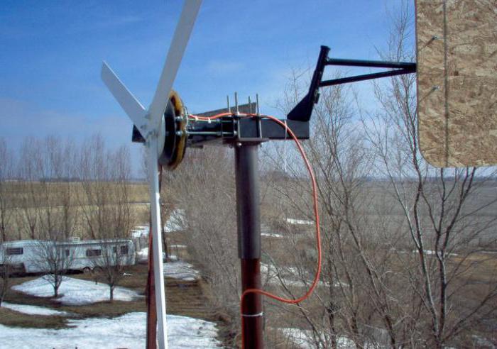
DIY wind generator
Having a vertical axis of rotation, it usually has from three to six blades. The design includes a stator, blades (fixed and rotating) and a rotor. Wind affects the blades, turbine entry and exit. Automobile hubs are sometimes used as a support. Such a generator on neodymium magnets is silent, remains stable even in strong winds. He doesn't need a tall mast. The movement starts even with a very weak wind.

What can be a fixed generator device
It is known that the electromotive force through the wire is generated by changing the magnetic field. The core of the stationary generator is created by electronic control, not mechanically. The generator controls the flow automatically, acting resonantly and consuming very little power. Its vibrations deflect the magnetic fluxes of iron or ferrite cores to the sides. The higher the oscillation frequency, the stronger the generator power. The launch is realized by a short-term pulse to the generator.
How to make a perpetual motion machine
On neodymium magnets, they are basically the same type according to the principle of operation. The standard option is already the axial type.
It is based on a hub from a car with brake discs. Such a base will become reliable and powerful.
When deciding to use it, the hub should be completely disassembled and checked if there is enough lubricant there, and if necessary, clean the rust. Then the finished device will be pleasantly painted, and it will acquire a “homely”, well-groomed look.

In a single-phase device, the poles must have an equal number with the number of magnets. In a three-phase, the ratio of two to three or four to three must be observed. Magnets are placed with alternating poles. They must be exactly located. To do this, you can draw a template on paper, cut it out and accurately transfer it to disk.
In order not to confuse the poles, marks are made with a marker. To do this, the magnets are brought with one side: the one that attracts is denoted by the sign "+", and the one that repels - "-". Magnets must attract, that is, those located opposite each other must have different poles.

Superglue or the like is usually used, and after the sticker is poured with more epoxy to increase strength, having previously made “borders” so that it does not leak out.
Three or single phase
A neodymium magnet generator is usually made to work with vibration under load, since it will not provide a constant current output, which will result in an abrupt amplitude.
On the other hand, with a three-phase system, constant power is guaranteed at all times due to phase compensation. Therefore, no vibration will occur, no buzz. And the efficiency of work will be fifty percent higher than with a single phase.
Coil winding and assembly
The calculation of the generator on neodymium magnets is mainly done by eye. But it is better, of course, to achieve accuracy. For example, for a low-speed device, where battery charging would begin to function at 100-150 revolutions per minute, 1000 to 1200 turns would be required. The total number is divided by the number of coils. So many turns will be required in each of them. The coils are wound with the thickest possible wire, since with a lower resistance, the current will be greater (with a large voltage, the resistance will take all the current).
Usually they use round ones, but it is better to wind coils of an elongated shape. The inner hole must be equal to or larger than the diameter of the magnet. In addition, the optimal magnet will be in the form of a rectangle, not a washer, since the former have a magnetic field stretched along the length, while the latter have a concentrated in the center.
The thickness of the stator is made equal to the thickness of the magnets. For the form, you can use plywood. Fiberglass is placed on its bottom and on top of the coils for strength. The coils are connected to each other, and each phase is brought out to be connected then by a triangle or a star.
It remains to make a mast and a reliable foundation.
Of course, this is not a perpetual motion machine on neodymium magnets. However, savings when using a wind generator will be provided.