A bit of backstory...
In the morning I got up and needed to go, the battery was discharged ... Bad ... I went and charged, the battery light on the panel did not light up, I did not look at the voltage, but in vain. I charged the battery for 40 minutes, so I went on business, didn’t turn off the car, came home - turned it off, didn’t start anymore, went to charge it. Spent the night charging. In the morning I sat down, started it - went on business. Charge 11.7 not enough (very not enough, after a night it is on charge), 30 minutes of driving the charge drops steadily 11,2
(the generator sucks instead of giving), drove up to the house, it won’t start - everything is clear, the diode bridge, the repair of the genadium.
Repair actually.
We remove the fastening of the tension of the generator, from above (key 10 and 13), loosen the swivel bolt from below (head 13), take off the belt, unscrew the three bolts securing the generator from below (head 15).
We pull out the generator, unscrew the rotary bolt of fastening to the block and separate the generator from the fasteners. Remove the generator cover. We unscrew the diode bridge (in my case, one diode burned out), a chocolate bar (eaten almost to zero), a capacitor. We look at the copper rings on which the chocolate brushes ride. We twist the anchor (humming).
I'm going to the grocery store
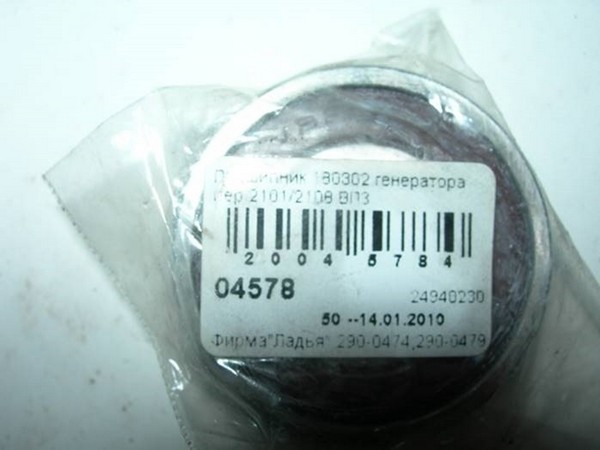
I take a diode bridge, a chocolate bar, and a couple of bearings (rear and front). There is not much to choose from, the choice in our stores is rather poor, I take what I have (you have to drive). In the future I will take a Nivovsky generator (130 Amperes) used, I will sort it out on normal spare parts..
Remove the generator pulley. We unscrew the head by 22 by inserting a screwdriver into the generator (do not wrinkle the petals much, if possible).
I'm starting to half. I put it on the bricks through the board, I tried to knock out for about forty minutes with WD-40, and as soon as I could, it gets skewed and in no way.
I sat down and thought... He put it on its side, inserted the open-end key sideways into the cut of the halves, carefully hammered it in with a hammer, and the miracle process began. First on one side, then on the other side. Then also with a screwdriver (it has a wider diameter), then with a larger tube and even more, until it is halved. Who will do the same carefully, do not drive the winding plates in! The anchor will not spin!. They split it in half.
I found a puller for large bearings in the garage, turned it on emery, and the puller became universal.
Took off a small bearing. I found three old unknown bearings in the garage, with their help I pressed in a new small one.
The big one was pressed out in a vise (sovdepovskie) with the help of 30 heads.
As a lever, I had to use a pipe otherwise, I was afraid the cover would burst from the load, but no, it survived everything. I pressed it back with a 32 head. Do not forget to core from the inside, I forgot - I had to completely disassemble the gene for this.
We assemble the bearings in place in the reverse order, rejoice at the silent gene. We look at the copper rings along which the chocolate brushes travel, if there are working grooves, you need to level them with sandpaper or a file (as it suits you). Without fanaticism! Otherwise, like me, going to the store is guaranteed to you. Why? Because, I had a large output, I grinded off a copper ring and it burst (Achtung!). I went home to sleep, 12 at night where can I buy it?
I went around the local shops and thank God I found one ring repair kit, I advise you to buy it immediately if yours are worn out.
Again, a complete analysis of the generator, pressing out a small bearing. We remove the plastic washer, bite off the wires going to the contacts of the rings, remove the old rings. As I understand it, it is not necessary to call which contact to which ring, because. these two wires are just two ends of the same winding and the rings, respectively, will be closed anyway (I could be wrong, correct me if so). We change the rings - we put them on a pulley, solder the limit switches (they were pressed in initially), I lubricated the contacts with lithol, put on a protective washer. We collect the generator. Before installing the diode bridge, we roll in new rings with a file or sandpaper (optional, but I did).
Do not confuse the bolts of the diode bridge! Three of them that go to the contacts, with textolite washers! Put a fourth without a puck in their place, get a short circuit, burn something!
We put it on the car.
We rejoice at the old-new generator. Personally, for me the voltage of the on-board network was 13.6 + -0.2 for the first day (with the dipped beam and radio turned on) on the second day 13.8 was stable (the brushes got used). Without light 14-14.2.
Good luck to everyone in repairs, on the roads and in life!
0:7 0:47
1. Removing the VAZ 2114 generator (the problem of the lower bolt on front-wheel drive)
0:1374 1:1881There was a need to remove the genes from the wife's car to replace the bearings. I quickly unscrewed the upper bolt of the belt tensioner, which fixes the upper bolt, but fell into a stupor on the lower one) quickly twisted the nut from the lower one, began to pull out the bolt - it rests on the side member. with a pull - but in the end he took it off like this - he put a jack under the box, raised that side, the side with the gene became lower, and he pulled it out), in my case it was not an option, piligrim-56 came up, advised him to cut it off. I decided to go home to warm up and look for solutions here. on D2 there are a lot of references to the saw cut of the bolt. So I decided to do it, only with my own small amendment /
1:3174
He pulled the bolt all the way into the spar, filed it right at the very exit to the middle, and in my case, with a large gas wrench, banged it a couple of times, straightening the bolt from the cut.
2:801
and voila - here he is the removed hero of the occasion) filed to the middle of the bolt took about 5 minutes at the most with an ordinary sheet of metal) the total time for removing the gene was 10 minutes.
3:17362.
In general, after washing the motor, the generator bearings rustled, my patience was enough for a week. I read the info on the replacement on the Internet, I found out that there are 5 types of bearings: 201, 202 and 301, 302, 303 2 types of front and 3 types of rear, or vice versa, I don’t remember exactly. I drove into the "Ladya" and decided to buy 202 and 302 they came out to me at 105 rubles, I was more worried that they would not fit. Here they are:
3:2436
Came to friends in the service began to shoot. I unscrewed the upper tension stud of the generator, removed the belt, unscrewed the bolt on the generator, removed the terminals from it, began to unscrew the lower bolt of the generator, but it does not come out rests on the spar, we unscrew the generator mount from the block 3 bolts by 15. As a result, here he is the hero of the occasion .
5:1616


We remove the relay regulator (brushes) by unscrewing 2 bolts.
We remove the plastic cover from the generator, we see the diode bridge. It is attached with 4 bolts.


here is a very important point. 3 bolts to which the terminals from the winding are attached, they have a textolite washer (it turned out by trial and error, more on that later), which prevents the winding from shorting to ground. We unscrew 4 bolts and remove the diode bridge.
10:432


We unscrew the 4 bolts that connect the 2 parts of the body to each other, having previously sprayed everything with a spray. I personally managed to unscrew only one bolt with a regular screwdriver. The rest I unscrewed with an impact screwdriver.
13:395
We put 2 marks on both parts of the case so as not to confuse later, unscrew 4 bolts, now we put screwdrivers on 2 sides between the 2 parts of the case and try to open it. The rear part is removed there, it is easier to get the bearing out of the plastic sleeve. The back part was removed, we put the front part of the generator with the anchor between the 2 bricks, screw the nut on the end, and beat from above in order to remove the anchor from the bearing.
In the end it should turn out like this.

We take the tighter front part, put it on something hard, take the head at 30 or 32, put it on the bearing and start peeling as much as we can, only gently so as not to break the front of the case.
15:353


We take a caliper and measure the old and new bearings. I was lucky, I bought the ones I needed.
18:168
We examine the contacts of the armature, where the relay regulator (brushes) is pressed, if there are grooves, then we refine it with sandpaper.
before:


We look at how to check the health of the generator in Murzilka.
21:2047
Next, we press the bearing into the front of the generator housing, with the same head for 30 or 32 powerful blows. We take a chisel and punch the bearing in a circle, you will see grooves there. We put the anchor in the front cover, put it again between 2 bricks, put on the rear bearing and carefully, with powerful blows to the center of the bearing, press it in until it stops. We put on the back cover, carefully pushing the winding terminals through it. Here, too, the main thing is to orient the winding terminals according to the fastening of the diode bridge. We put on the diode bridge, bend the winding terminals to it and tighten 4 bolts, twist 3 bolts with textolite washers, where the winding terminals are, take a tester and check if the winding closes with the case. If not, then everything is correct. We put on the relay regulator, a plastic boot, fasten the generator into place, tighten the belt, start it. We look to see if the battery discharge lamp on the instrument panel is on.
22:2160In my case, it was on fire and the generator heated up in 10 seconds so that it was impossible to touch it. I took everything off again and it turned out that I mixed up the bolts for fastening the diode bridge and my winding punished for ground. Good thing it didn't burn anything. I go and enjoy the silence.
22:490I decided to replace the positive wire from the generator to the battery, the negative wire from the battery to the engine and to the body, throw the mass from the generator housing to the body. In the process of work, I also replaced the positive wire from the starter to the battery.
Previously, before this large-scale lesson, I purchased three meters of wire in a thick rubber sheath, with a cross section of 25 squares. Although three meters was not enough for me, I had to take three and a half. Fortunately, there was a piece of such a cable in the garage. A meter of cable cost me 115 rubles, a total of 345 rubles. three meters.
I also bought six new thick wire lugs. I chose copper and tinned tips, with 6mm holes. I figured that it would be needed with 8 mm holes, but I didn’t know how many in advance and decided to take these, and in the process of work, which ones would need to be drilled up to 8 mm. The price of one tip is 20 rubles. All six stood at 120r.
I also bought, just in case, six copper sleeves, but they were almost never useful to me, only one. But nothing, they will come in handy on the farm. The price for one sleeve is 15 rubles, for six in the end - 90 rubles.
At the same time I decided to replace both terminals on the battery. The old ones didn’t inspire confidence in me lately, they’ve already let me down a couple of times, and even they are being tightened with a hexagon, but I’m already fed up with it.

Old terminals. Quite good, but I didn't like it very much lately
23:643
Wires, terminals, lugs, sleeves (almost not useful).
24:1262I chose the thickest ones, so that they were coated, had a large main input for power wires and additional inputs for additional equipment, and it is imperative that the tightening be an ordinary open-end wrench or box wrench, it’s more convenient for me.
24:1690
Here they are, beauties
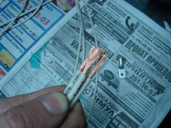
25:36To begin with, I rummaged through the grid, in the hope that someone would tell you which of the three wires of the generator goes to the battery. Of course, I guessed that the one that goes alone, and not the one that is doubled on one of the two terminals, is what I was looking for, but still, to make sure, it’s a serious matter. I never found anything. Basically, many people leave the old wire and pair it with a new one. This option did not suit me at all. In general, I found the wire I needed on my own, just from it it was already clear that it was necessary to leave it nafig, it had already burned out and dried up. Pulled it out from under the hood
25:1063
Here it is, the one that goes directly from the genes to the battery.
26:1651Cut off a new wire along its length
26:1716
Old and new wires. Comparison.
27:65I cleaned the end and irradiated it with a soldering iron that I have in the garage with a power of 300W, he coped with this task easily. So that the wire does not oxidize inside.
27:371
After that, put a tip on it
28:967
Tip in place
29:1514Well, and then, I carefully squeezed the tip in a vise, warmed it up with a soldering iron inserted into the wire, so that they merge into one whole and insulated with a thermotube in the color of the positive wire, for convenience. At the same time, I drilled a hole in the tip to a diameter of 8mm, since the bolt on the generator (I have a Priorovsky 115A) has a thickness of 8mm.
29:2132
Plus is almost ready
30:548According to the same scheme, then I attached all the tips on all the wires.
At the same time, I replaced the tip on the second and third twin wires of the genes, as it turned out that the tip was dead, I didn’t like it

The second and third wire genes are paired on the same tip. Now it's okay.
31:1577While I was working with this wire, I paid attention to the power wire of the starter - it was still normal, but already pretty stiff. I decided that I would replace it. Here, just the wire, I did not count on it. I found the same wire in the garage, a piece, and made a new one, for the starter. Here, just one sleeve came in handy, since six pieces were not taken into account also for the starter. I made a tip out of the sleeve, irradiated it and everything. After that, I fixed both wires (starter and generator) in the positive terminal and put a corrugation on them, for reliability, all the same, the current through them is not sickly.
31:2574
This is how the finished power wire of the generator and starter turned out =)
32:633In the same way, I replaced the ground wire from the engine and body
32:741
Wires of weight of the engine and body
33:1312
Ready-made negative wire of the engine and body
34:1904In principle, it was possible not to put a mass wire in a corrugation, but I had a corrugation, so why not put it on, it looks better and it won’t be superfluous.
It's time to put all these things in place. Connect the positive wire to the alternator

It's expensive to see
35:552Then a mass wire to the engine and to the body
35:637
Mass to the engine ready
36:1197It was the turn to deal with the mass wire from the generator housing to the body. Everything was immediately clear with the place of attachment to the gene, but I did not immediately decide on the place of attachment to the body. Mounting option for a screw near the washer barrel, I did not like. Dead somehow and not reliable. Moreover, the alternator belt tension will interfere with checking. I didn't like this option. Decided to screw on the headlight mounting bolt. It is more comfortable and looks more aesthetically pleasing. I almost forgot to say that I put toothed washers under all the tips so that their contact with the body and engine was optimal. Also here, I put a toothed washer on the headlight bolt, and only then tightened the tip of the wire. Although the headlight bolt has little to do with the mass of the body, the wire was well powered to ground and reliably through the toothed washer.
36:2638
Alternator ground wire to body. One terminal with a 6mm hole for the headlight bolt, the other with an 8mm hole for the alternator bolt.
37:741![]()
I think everything can be seen in the photo how the gene mass wire is located, where it is screwed.
38:1397When I finished everything, I finished with the injector, I assembled everything, screwed the terminals into place to the battery, lubricated them with a little grease at the point of contact with the battery
38:1645![]()
39:17
Started the engine. By the way, before this operation, charging on a cold engine, according to the readings of the tidy, swam from 13.8 to 14.2, and on the warmed up one, in general, lately, according to the tidy, fell to 13.3,12.9. Because of this, the battery began to charge poorly and once I even had to charge it, after which I forgot to wrap its plugs and lost one. Now looks like a wounded man with a gag.
The result of the work, on a cold, running engine, but not with consumers turned on, according to the readings of the tidy, charging became 14.6 stably.

Charging on a cold engine. Stable 14.6
40:1480After the engine is fully warmed up, the charge drops to 14.3-14.4
40:1590
The charge on a fully warm engine does not fall below 14.3
41:121Then I turn on the backlight (by the way, my backlight is not stock and takes a much larger load, the loss in the backlight is 0.4 volts at once), fogs, light, stove in the first position (I have the most running one, it’s enough for me, fries well) Charging is at least 13.8 according to tidy.
41:632
Charging on a warm engine with the backlight on, headlights, PTF and the stove in the first running position 13.8
42:1347This is the most current mode of my car now - the stove in the first position, light, fogs and lights. For optimal battery charging, charging directly to the battery should be at least 13.6, I think 14.52 will not boil and is enough. In short, I'm happy.
42:1804Total:
1. Wire 25 squares, 3 meters at 115 rubles. - 345 rub.
2. Tips 6 pieces for 20 rubles. - 120r.
3. Sleeves 6 pieces (only one was useful) for 15r - 90r.
4. Battery terminals pair - 530r.
5. Soldering iron, tin, heat pipes and other tools are always available.
If I had a stock backlight, then I think the charge would be even higher, since the backlight takes decently from me.
In the future, I plan to replace the dual wire of the generator, I think it will not hurt.
P.S.2 To everyone who did not understand from the measurements - the readings were taken from dashboard not directly from the battery. And that's a big difference. The tidy shows the residual voltage already with all the losses. And not the first current at the output from the generator.
Measurements from the battery with consumers not included show 14.62-14.65 on a cold engine and 14.52 in general with all consumers turned on at full power. Isn't that enough? 8) On a warm engine, I have not yet taken measurements, there is no time.
So far, I have made measurements only on a completely unheated engine, since there is no time for this yet. I couldn’t do it earlier, because the multimeter treacherously died at the wrong time.
The first measurement is a running engine without consumers turned on.

First freeze. The engine is cold. Consumers are not included.
43:1072The second measurement is GENERALLY WITH ALL consumers - Illumination in the cabin and outside, High beam, Front PTFs, Rear PTFs, Heated rear window, Heated mirrors, Stove in the third maximum position, Music (without subwoofer).
43:1475
Second freeze. The engine is cold. All consumers are included. I decided to replace the twin wire of the generator, but have not yet made a final decision on how best to deal with it. To begin with, I found it in a block near the mounting block
44:2418
Here he is, dear. Or rather - they are two fat, pink.
45:605The question arose that if instead of two double, one or more wires of a larger cross section are thrown, then a problem may arise with how to install them in the block. You can of course without it, but I do not like this option. And one moment. Since the wires will be much thicker, I am afraid that there will be no loss on such small terminals. I found an empty space in the block, there are thoughts of using it. Perhaps I’ll consider this option - I’ll throw three wires of a larger cross section than my own, but not very large and spread them over three mothers, in total I get one larger cross section.
45:1711
The size of mothers does not inspire for feats in any way.
46:96I decided to remove the block and see what's what. Took it off the car and took it apart. The state, in principle, is nothing, but according to appearance board, it immediately became clear that water gets into the block from time to time, and this is bad. The board oxidized in some places of soldering and the varnish began to peel off from some tracks.
46:636
An autopsy showed that water was getting into the block.
47:1227The white wire in the photo, I once duplicated one of the tracks, since the varnish came off it, it oxidized and there was a suspicion that it was short. Cut it off and replaced it with wire.
47:1542
The second side of the board. Well, it's more decent.
48:84I figured out where both wires from the generator go. It turned out that they come to a common plate with "dad" terminals and, by the way, the empty contact of the pad just also comes to this plate, this is already good ...
48:452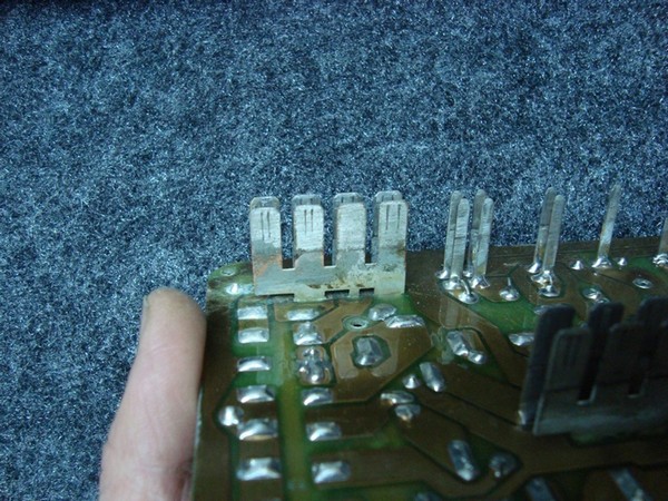
Here is the same contact plate. Both wires from the generator come to it and there is one more free contact.
49:1164The only thing that confused me was that the fastening of this plate to the board was thin, as it seemed to me, legs. No matter how the losses lurk here ... 8) On the top photo you can see only the central antennae of the plate that it is thin, and on the bottom photo, you can see that all three antennae are the same - thin.
49:1676
All three antennae are thin and connected on one jumper.
50:102It also became clear that all three antennae are soldered to one common jumper. I also didn't really like the cross section. Because in fact it is a continuation of the introductory double wires from the genes and does not even correspond to their cross section. Immediately such a concrete brake right at the beginning of all consumers. I think I'll try to increase it.
I also found that on one of the plastic halves of the mounting block, some "daddy" terminals with jumpers between them are fixed. I also did not like their jumpers, they are rather weak in my opinion. Maybe not all, but I would strengthen everything.

Jumper terminals. I don't think it hurts to be stronger.
51:1758In general, having dealt with all these matters, having found out from a part what was happening, for a start I decided to wash the board and covers. Because special means I don’t have a board to clean, so I washed it with plain warm water using an old toothbrush. Then I dried it well on the battery. Almost all of it was washed off, although in some places oxide still remained, I think that it was formed during drying. Well, until I began to pay attention to her, then I'll deal with her, but for now I took up the soldering iron.
First of all, I decided to start from the very, as it seemed to me, easy and fast - from the jumpers on the block cover. Two options arose in my head, either to completely replace them with thicker ones, or to duplicate them with a wire of a slightly larger cross section and thereby reduce their resistance. Decided to go the second way.
I found in the garage a copper wire lacquered with a protective varnish of a slightly larger cross section than the jumpers, with the help of wire cutters and pliers, I began to give it the shape of jumpers. I'll tell you this is a dreary task ...

It seems to work.
52:542I made several jumpers, then soldered them in parallel to my relatives.
52:663
It seems to be similar, only gold
53:1227I worked with them from seven in the evening until three in the morning.
Here is the result, below.

I decided to cover the soldering points later with a special varnish so that they do not oxidize if suddenly water gets in. But this is later, when I finish all the work on the block.
Then I decided to replace the jumpers on the board. Pay attention to how dead they are. Perhaps they are enough, of course, in principle, but I did not like them at all. On my board, they are made with wires with blue and black insulation, you can see it well in the photo

I decided to replace the stock jumpers
55:576In the garage there was a single-core, copper wire of 2.5 squares. The photo below shows how much thicker it is than the standard jumper, and in general you can see how thin it is, just a kapets.
55:879
On the left is a replacement. On the right - the one that was on the board.
56:1478After I prepared a new jumper, I came across the fact that the old holes in the jumper board do not fit the new one, they are too small. After thinking and carefully examining the place of the battle, I determined that the holes can be safely drilled out and this will not create interference such as closing the tracks during soldering. For this case, a 2.2 mm drill came in handy. I inserted it into the screwdriver and carefully drilled the holes
56:2240
Using a screwdriver and a 2.2 mm drill, I drilled regular holes. Then, I soldered the first jumper and everything worked out with a bang.
57:734
First change, result. The difference from relatives is noticeable to the naked eye. Then, I did the next one and it went, it went, it went.
58:1463
rushed
59:1992So the jumpers are almost all replaced
59:2074
Result. Almost all jumpers have been replaced.
60:584 60:948I soldered all the new jumpers, instead of relatives. The operation to replace them was quite successful, although the process itself took a decent amount of time. Then I decided to strengthen the main power jumper, the one that connects the input connector of the terminals from the generator to the block, since it seemed to me too thin in relation to the cross section of the input wire. Why did he take a piece of copper wire with a cross section of about 6 squares, bent out of it exactly the same jumper as his own, irradiated it thoroughly
60:1809
Additional jumper to native.
61:59And soldered it over the old one. I didn’t solder it along the entire length, since I don’t consider it necessary, I soldered it well in those places where it connects to the terminal connectors. So that patency to them is not hindered by narrowing in some places along its perimeter.
61:513
Soldered a new jumper. She fell into place paired with her own, as she was here.
62:1154Then I decided to solder all the legs of the terminals that are connected to this power jumper, since the terminals themselves, in principle, are more or less wide, but their attachment to the jumper is very narrowed and is in the form of thin legs. These very legs I strengthened in diameter by soldering with tin so that they were no smaller in diameter than the terminals themselves. My camera does not pull from such a close approximation, so as I was able to take a picture, it turned out. In the second part there is a photo of the legs of the terminals attached to the jumpers, and here are their photos already reinforced by soldering.
62:2164
Soldered and enlarged input connector legs.
63:600There are three on the input connector of the terminals of these same legs. Two pass through the board completely in its entire width and then sharply narrow, and the middle one narrows on the other side of the board and then enters the initially narrow one. I thought what to do with it, but then I spat, and decided to leave it as it is, and direct the entire load to the remaining two, and strengthened them as much as I could.
When I finished with this, there was an idea to solder all the tracks of the board in order to strengthen them and increase their volume for better conductivity. Yes, but here it’s such a thing that this work, or rather work on the side where the terminals of the fuses, relays are located and all the jumpers are soldered, had to be done before the new jumpers were soldered. Otherwise, they get in the way, and in order to do this, they need to be soldered again and all that. And I spent so much time on it. In short, I screwed up a little with this case. I decided, okay, I'll try to do without this procedure for now. For prevention, I reinforced the first track, the one that comes from the input and to the first terminals of almost all fuses

Reinforced the track from the connector to the fuse terminals.
64:607On this, work with the block had to be suspended, since a machine was needed and the block had to be put in place. Of course, I couldn’t help but pay attention to the readings of the tidy … I was worried, of course, that all the work had gone to waste and the time spent on it was wasted. Started the car. The tidy readings, as before, remained no lower than they were before - 14.6
64:1261
The gauge readings on a cold engine have not changed since the first modifications. Remaining at least 14.6
65:1963Well, everything is clear here. After the engine was fully warmed up, the tidy readings dropped to 14.4 8). And this was already at least a little, but more than before the block was soldered. Prior to this, the tidy readings (after replacing the wires of the gene-battery + mass) were 14.3-14.4, 14.3 was more stable.
65:2445
Indications tidy after a full warm-up of the engine became 14.4. Before working on the block, they were a little less than 14.3
66:711With a trembling hand and numb fingers, I began to turn on the consumers. 8) Turned on - all my backlight (far from stock, gives a very strong drawdown), high beam, front PTF, rear PTF, heated rear window, heated mirrors, heater (stove) at full power in the third position, music (without subwoofer) ... 8) Tidy showed me 14.0
66:1312
Fully tidy readings with all consumers at full power, with a warm engine, 14.0. I tried to turn off the heated rear window, since it takes a very large load, even more, it seems to me, than the stove, the tidy readings rose to 14.1
67:2302
Indications of tidy on a warm engine, with all consumers turned on, but with the heated rear window turned off, 14.1
68:739Well, I very rarely drive with a heated rear window, mostly after sleet when leaving the parking lot. So I do not take into account its load, basically it is not included.
The work didn't go smoothly. 8) I skated for a day, no problems were identified in the operation of the unit, and the tidy began to please with other numbers.
I decided to complete the work on the block for the time being, since the result obtained is now quite enough for me.
I took it off the car again, disassembled it and filled it well with varnish twice, so that no moisture that got into the block would mess up my work.

Lacquered the lintels of the lid.
69:59I even missed as far as possible all the terminals of the connectors and fuses, at least from the outside, so that they also do not oxidize, well, at least to minimize oxidation.
69:385
Filled the board with varnish from the heart.
70:943
I spilled the fee on my conscience, twice. And he varnished the outer sides of all the terminals, as much as possible. I dried the board well on the battery. Then he began to assemble the block. To prevent moisture from entering the block, I decided to coat the joint of the halves of its body with silicone sealant. I think that if it is necessary to disassemble the block, it will not become a big obstacle when it dries up, and at the same time, water will not pass into the inside of the block.
71:2240
I smeared the joint of the halves of the block with ordinary black silicone sealant.
72:647I also decided to smear the location of the terminals of the upper connector of the block with sealant, since they most likely got the most water into the block. I smeared sealant on the bottom of the terminals, in the skirts of their glue, with which they were fixed from the factory in the top cover before disassembling the block
72:1137
I smeared the bottom of the terminals of the upper connector with sealant. Through them most of the water enters the block.
73:1817And he assembled the block into a single whole.
73:1873
Collected block. Then I smeared the seam again with sealant for reliability.
74:130I put it on the battery in assembled form, until the next day, so that it dries well in warmth. And while the block was drying, I decided to start replacing the wire from the generator to the mounting block. Having previously bought 5.5 meters of PV-3 wire with a cross section of 6 squares and a tinned terminal to it, the same as I put on the wires in the first part, with a diameter of 25 squares. The price for one meter of wire is 31 rubles, the price of the terminal is 20 rubles. And also, I was lucky, I found a car corrugation, and even just the diameter I needed and not in pieces of one meter, but in a cut, which footage I need. 8) The price of one meter of corrugation cost me 32 rubles per meter. Why did I need 5.5 meters of wire? The topic there is such that it is not possible to shove a larger wire into the connector of the block, which includes wires from the generator. The native wire has a cross section of approximately 4 squares, and it is doubled, that is, its total cross section is approximately 8 squares. I decided to increase the cross section of the wire and add one more, third wire to the existing empty slot of the connector. And that three wires with a cross section of 6 squares each in total gave 18 squares of a total cross section.
I folded the wire in three and cut it into three identical pieces, the length of each turned out to be approximately 1.8 m, this was enough for the entire length from the generator to the mounting block, even with a little extra margin.
Stripped the ends of all three wires
I stripped the ends of all three wires, folded them into one cable.
75:617covered them with tin, put on the tip, warmed it up well, then quickly clamped it in a vise and extended it heartily. Then I insulated the whole thing with red heat shrink tubing. For convenience and Feng Shui, "plus" after all.
75:1031
He warmed it up, squeezed it out and closed it with a red heat shrink tube. I pulled all three wires together with thermotube rings after a certain distance so that they were in one bunch
76:1864
Almost ready new cable from the generator to the unit. Then, I cleaned the other ends of the wires and soldered the "mother" terminals to them. I also insulated them with a red thermotube so that everything was a bundle, in every sense.
77:383
This is how the Serpent-Gorynych turned out
78:961Well, and finally, I put a corrugation on the resulting cable. He pressed it along its entire length at an equal distance with rings from a thermotube, and closed it at the ends with a red tube.
78:1271
Ready-made cable from the generator to the unit.
79:1850I did not remove the old wires from the generator to the block. I looked, there is too much work there to pull them out of the common harness and from the corrugation. I decided to just turn them off, cut off the ends so as not to hang out and not embarrass. He stretched the new cable along the location of the old one, securing it along the length with plastic clamps.
The next day, the block was already dry well, put it in place. For prevention, I passed the bottom of the extreme edge of the block with a sealant so that after installing the block under it, water would not get into the cabin. Connected a new cable and everything, in principle.
By the way, I replaced the corrugation on the previously made wires of the masses and pluses of the battery. Photos of wires with a new corrugation in the first part of this topic, who are interested, take a look.
Started the car. And, to be honest, my readings on the tidy have not changed at all. The only thing is that when such powerful consumers as the heated rear window and the stove were turned on, the short-term power surge decreased noticeably, I felt it right away. But the residual voltage, according to the readings of the tidy, did not affect the replacement of the wire. Well, at least to reduce the jump, the work was not done in vain.
In general, the greatest increase in voltage and a decrease in losses occurred after replacing the wire from the generator to the battery, replacing all the wires of the power masses, installing additional. generator ground wires and soldering of the mounting block. Replacing the wire from the generator to the unit did not give a tangible increase on my car.
79:567If someone has a desire to strengthen the tracks of the board, then I think that this will also make its own changes to the tidy readings. I haven't gotten around to this yet, but I'm very happy with the results.
79:930But the readings taken from the battery on a fully warmed up engine, with absolutely all consumers turned on at full power, I don’t know about anyone, but for me it’s enough to fully charge the battery and so that it doesn’t boil over my eyes.
79:1346
Indications. Fully warm engine. All consumers are turned on at full capacity. 14.3
80:2022Outcome:
1. Wire PV-3 with a cross section of 6 squares, 5.5 m long. - 171 rub. (price per meter - 31r.)
2. Tinned terminal, for a wire of 25 squares - 20 rubles.
3. Terminals "mother", three pieces - were in stock.
4. Heat shrink tubing in different sizes and colors - was in stock.
5. Plastic harnesses, a soldering iron with solder, and other tools are always at hand.
6. Car corrugation, diameter 15.7 mm, length 5.5 m (for all previously replaced wires and this cable) - 176 rubles. (price per meter - 32 rub.)
The car often ran out of battery, which is less than a year old. The voltmeter showed low voltage. After reading on the Internet about increasing the number of volts produced by the generator, I did the same as many do.
80:1332Initial voltage when I just started the car (all buttons, stove and music are off)
80:1497
So, we need: a thick wire (I have an extra one from the subwoofer) and 4 terminals. Soldering iron and electrical tape
81:193
I cut off the wire, soldered the terminals to it on both sides, insulated the place of soldering just in case
82:880

Next, remove the negative terminal from the battery. We take the wire we made and fasten it with one end to the generator, the other end to the mass of the body, I screwed it to the bolt near the washer reservoir windshield(it was possible to the bolt that holds the headlight, but no matter where)
84:2398
close-up
85:537
general form
86:1065The voltage increased to 13.5 - 13.6 V.
86:1133
The next step is to connect the extra ground to the battery. On the negative terminal of the battery, there is a thin black wire (I even had some kind of factory label on it). We unscrew this wire from the terminal, put the second, our home-made, wiring under it, after which we twist the wire, along with the factory one. We look where the factory wire goes, it goes to the left wing, parallel to the battery. We unscrew the wire from the mass (from the wing), wipe the nut, the terminal of this wire, and the washer with a rag. We fasten the home-made wire and on top of it the factory one. Those. everything we have. got two wires going to ground from the battery. The factory one can be removed if desired.
87:2844

RESULT:
89:1036
I'm glad that at least a little managed to increase the battery charging from the generator. Closer to winter, I plan to install a "Three-level voltage regulator".
90:1799Howled somehow in the parking lot generator. He spent a couple of seconds and fell silent. Then again. I looked under the kakpot - the belt is intact, the generator outwardly is absolutely in order. But the onboard voltage is 12.6V instead of 13.8V. Urgently in the garage, while he can go)
I remove the generator, clean the sticker. Installed Generator ELTRA 5102.3771, 14V 80A. I will not dwell on the removal and disassembly of the generator in detail, all this is described in detail in the manual.
The result of the inspection: some of the diodes in the bridge are charred and smoked, the bearings play, the slip rings are worn off almost to the insulation.
Bearings are pressed out and replaced. Here are examples of suitable ones:
Rear:
Nachi 6202DDUCM
Koyo 62022RSCM
Front:
Nachi6303 DDUCM
Koyo 63032RSCM
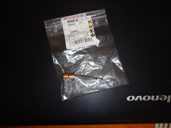
I also bought and replaced the diode bridge and the relay-regulator without any problems, but with contact rings there is an ambush, they are not for sale anywhere. And if there are VAZ generators, they are not suitable for this ELTRA.
I sat down at the catalogs and began to study the proposed rings. A long search finally led to success. Here is the code for suitable rings: 120950, manufacturer IKA.
I soldered off the old rings, and they easily removed from the rotor. Comparison of old and new rings. Pay attention to the development of the lower ring:
91:1453
We put on new rings, having previously smeared the landing ring with cyanoacrylate, solder them and cover the bare places with varnish:
92:2188
We put on an insulating washer:
93:559
The rotor was taken to the groove of the rings to remove the beats:
94:1167
Assembling the generator:
95:1714
All fasteners were replaced with stainless ones, all connections were carefully insulated, and the generator itself was cleaned.
96:1816. Diagnostics of the operation of the VAZ 2115 generator - measurements
I have a problem with voltage - at XX it seems to give out the norm, but very slowly gaining this norm after turning off the consumers.
96:512Here are the measurements
After a night of downtime:
The engine was not started, the consumers were switched off.


After I rode not much, about 5-7 km. The car is running. Included dimensions and near.
98:1834

As you can see, the readings are disappointing, if you also press the brake, then there are generally 12.7-12.8, and this is not good at all.
100:709What we need to remove the generator:
Key/heads, etc. 8, 10, 13 and it seems like 15
Starting to remove the generator
The first thing to do is to remove the terminal from the battery, you can even remove both so as not to accidentally short something.
Well, then we remove the terminals from the generator.
One terminal is made according to the principle "mother" "father" - it is simply pulled out of the generator.
The second terminal is screwed with a nut, this nut is under a rubber plug. My gum dried out, in the photo, in principle, everything is visible.

Terminals/contacts on generator
101:58Then we unscrew these bolts in order
101:140
And we shift the generator to the engine to remove the belt.
102:748 102:1046

Be careful, after you unscrew the third bolt, the generator will fall, keep this in mind! You can’t drop the generator, but maybe you can, I don’t know, but it’s better not to do this!
104:297In principle, that's all, now the generator is in your hands.
104:399
There is not much text yet about what not to do and how I unscrewed the bolts.
105:1038What not to do:
105:1078There is a bolt / stud on the bottom of the generator that DOES NOT NEED to unscrew! You can only loosen it a bit, but this is not necessary)
Unfortunately, there is no photo of this one, but I circled the place where it stands.

They say that to remove the generator, it is enough to unscrew this particular bolt, but this is not so. This bolt only tightens the inner bushings, which in turn hold the alternator to the alternator mount to the engine block. In short, even if you pull out this bolt, you will not remove the generator either.
106:2445Here is the pin
106:31
She rests on the body and pulling her out does not work. I also tried to push the engine, but nothing.
107:721
Briefly about how he unscrewed the bolts, took the head and the collar, inserted it into the bolt and shoved it with his foot. Otherwise, no way - just a kapets how uncomfortable with your hands.
108:1479
This time, I called him to make sure that the generator itself was still alive.
109:2198So, let's go in order.
109:46What needs to be done to check the generator, well, firstly, you need to remove the plastic cover from the generator under which the diode bridge and the relay / voltage regulator / brushes are located
109:363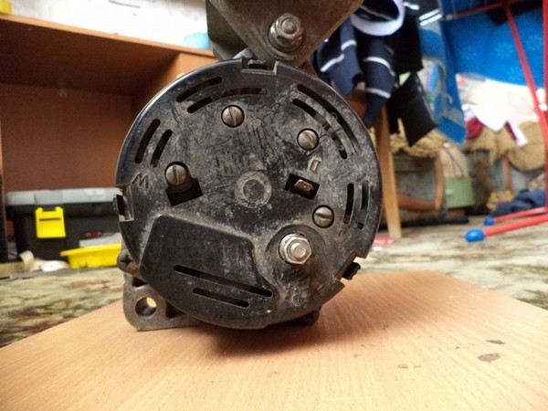
Remove the cover
110:901We get such a picture (just don’t lose the washers)
110:999
Diode bridge and voltage regulator
Now unscrew and disconnect the voltage regulator


Look at the condition of the brushes
113:559
Bottom brush 11mm
114:1100
Top brush 12mm
115:1643And then the question arose: what is the length of the factory, new brushes? I didn’t find anything sensible on the network, but I found only that the minimum is 5mm. These brushes are already 7 years old and have 67,000 miles. Go ahead. We remove the diode bridge. You can not shoot, in principle, but I took it, I was just interested. To remove the diode bridge, it is enough to bend 4 contacts. Some generators may have 3.
115:2320![]()

Generator check
117:1070We check the resistance of the rotor winding with a tester by connecting it to slip rings. The resistance should be approximately 3-5 ohms. If the readings on the tester show infinity, then there is a break in the rotor winding and it must be replaced.
117:1538I have 3.2 ohms - the norm.
117:1578
To test additional diodes, connect the “positive” (red) probe of the tester to the terminals of the stator winding, to which the terminals of the additional diodes are soldered, and connect the “negative” (black) probe to the opposite terminals of the additional diodes. If the diodes are good, the tester will show a resistance of 550-600 ohms.
118:589About the norm. Instrument error + probes are poorly pressed.
118:697
Checking rectifier diodes. To do this, set the tester to the resistance measurement mode and connect the “negative” (black) tester probe to the “plus” terminal of the generator, and connect the “positive” (red) probe in turn to the eight contact terminals of the diodes. If the diodes are good, the tester will show a resistance of 550-600 ohms.
119:1820I did it this way, the idea is the same
119:1913
Check the generator stator windings. Alternately connecting the ohmmeter probes to the terminals of the generator stator winding, we check the winding for an open circuit. In the absence of a break in the generator stator winding, the ohmmeter will show low resistance (about 10 ohms)
120:458In my case, it is 0.9 ohm - also in order.
120:534
So, I didn’t check the brushes themselves, since they need a battery and a light bulb, and something else.
121:1206I cleaned every contact I could clean
121:14301. Cleaned all the contacts on the generator
2. I cleaned the fasteners of the generator to the engine block (As I was told, this is the "mass")
3. Cleaned up on the engine block those places where the generator fasteners are pressed (As I was told, this is the "mass")
4. Cleaned contact "D" (wire in car)
5. Stripped the power wires that are connected to the generator.
6. I also cleaned the terminals on the battery
Now some pics
121:41

SUMMARY OF WORK:
I connected everything, started the car, the BC gave readings at 14.2v
I rode a bit around the yard (200 meters, because all the docks on the car remained at home, I decided not to risk it. I turned on the music, as usual, quietly, so for myself and the BC showed 14.1 - 14.2v
Included dimensions - 14.1
Turned on the neighbor, and lo and behold! - 13.9
It used to be 13.3v - Cleaning the contacts was successful and helped a lot. The work was not done in vain, it pleases.
123:1783I didn't change the brushes.
123:1817As you remember, I wrote that the length of my brushes is 11 and 12mm. I was very interested in how long the new brushes are - so I did not find it. The critical minimum is 5mm!
123:2123The photo, which shows a small output on the generator anchors, in principle, the output is small.
123:181
It's no secret that with the voltage in the VAZs, not everything is going smoothly. BUT you will be calm. you have on board TWO voltmeters - TROTSKY
1 - tidy VDO
2 - Trip computer. They, having agreed, make you + 0.2V to the on-board voltage.
And when you cut through it, dances begin with a rise in tension. People are trying to raise it in various ways.
Why does the voltage drop?
In a conventional voltage regulator there is a circuit that reduces the voltage when the temperature rises, BUT this circuit is inside the regulator in the generator, and the generator warms up along with the engine.
In the summer, okay, the voltage dropped and okay - the battery will not boil. And in winter? - not recharging, not starting, overdischarging, frozen battery ... did not save the battery.
What they do:
1. solder the diode to the regulator in a gap.< 20руб. (зависимость от температуры двигателя остается)
2. buy a three-level regulator> 300 rubles.
3. Refinement of the standard regulator circuit - 120 rubles. This is with the purchase of a regulator (depending on engine temperature)
4. Thermally optimized regulator.
Problems may arise with the purchase of the latter, in Tula in many stores they do not understand what I want from them, because they have not even seen this regulator.
124:849Meet the killer of 3-level regulators.
124:935
Voltage regulator Thermally optimized (Renato) 61.3702-05. (packaged)
125:1577
Instruction 1 side
126:40
Instruction 2 side
127:588
reverse side of the package
128:1147We carefully look where it is applied. The information on the manufacturer's website is contradictory.
128:1304
Main page
129:1848
regulator page
130:45I will not write anything, "10 differences" you will find yourself if your eyes are in place.
130:170In addition to the instructions, the package contains
130:236
Regulator, temperature sensor, plug, block, ties
131:837
more contrast
132:1379
Standard regulator and thermo-optimized
133:1977
Front view
134:24
Even the mounts match.
135:581
on the back side
136:1126
![]()
Soldering contacts (by the way, varnished - that's good)
138:95What are the plushies?
1. Set and forget (if it doesn't break)
2. There is no need to switch voltages like on the 3rd level.
3. More competent battery charging in cold and hot weather.
4. Higher voltage when the car is warm.
5. The battery will last longer (debatable, but the chances are greater)
Graph of voltage versus temperature.
It's no secret that in cold weather you need more voltage to charge the battery, compared to warm weather. (battery features)

Graph of voltage change from sensor temperature
139:147714.7V at -20
14.6V at 0
14.4V at 20
14V at 50
13.8V at 60
At the same time, not engine temperatures, but battery terminal temperatures, which is much better than monitoring the temperature of the generator case.
Demonstration of operation and voltage adjustment.
139:1898Controller operation when the sensor temperature changes.
139:2000In the end, I would like to make a comment to the manufacturer.
139:89

Slit 2 return
141:115211. Installing a thermally optimized voltage regulator (Renato) 61.3702-05 VAZ 2114
We will talk about voltage, current output of the generator and other things.
I have the opportunity to simultaneously measure the voltage and currents of battery charging and Auto consumption.
Now about everything in order
141:1655
Size comparison
142:38Now I’ll tell you why, the tablet of the new regulator is larger than that of the stock one - the result is that the cover does not snap into place until the fasteners snap into place.
142:298
Places where it interferes
143:839You can see the results of sawing near the car, which were unsuccessful ...
143:979
inside view
144:1511I took it home, called a soldering iron.
144:1570
Melted excess plastic
145:45
Cooling holes
146:595Tried to expand on the street and quickly - the result is not aesthetic.
146:718
hole filled with hot glue
147:1279
Perhaps in vain, let's hope it doesn't leak (glue)
148:1876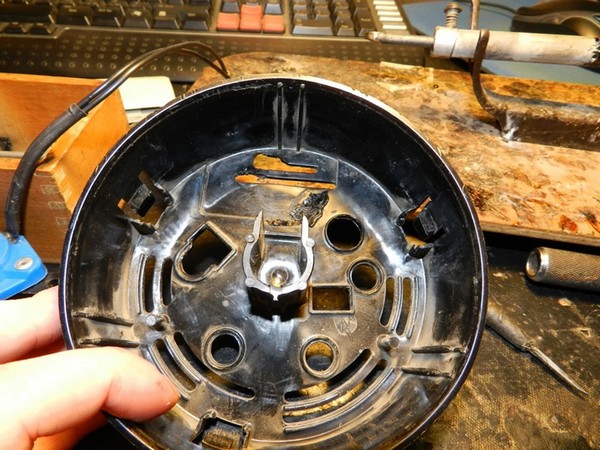
Here's what happened in the end
149:41All this fuss made it possible to snap the lid on 1 latch out of 3. This is better than 0/3 in any way.
149:213After installing the regulator, I connected the temperature sensor to the positive terminal of the battery.
149:363Now measurements
149:392
Comparison of generators. (found on the internet)
150:976This picture is about the current output of the generator, see how many amperes and at what speed.
Here some people think I will throw out my 90A generator and buy a 120A priar gene (or 125A, I don’t know). All this, of course, is probably not bad, BUT if there is an old-style regulator higher than 14-14.2V in that generator, you will not see it! Yes, and with the warming up of the generator and the engine compartment, the voltage will decrease - temperature compensation.
Watch the video with the included annotations!
150:1769 150:1779Well, about tookotdacha
150:1818150:1824
When the generator does not have enough power due to high consumption, it begins to dip in voltage, while part of the current begins to be taken from the battery.
But with an increase in speed, everything is restored.
Conclusion: it's stupid to wait for 14V at idle!
150:83For comparison, I measured the consumption of my "navigation lights"
150:189Stock regulator from generator
150:254150:260

generator 90A
151:794![]()
Problem Generator - K1216EN1
152:1354
This generator of problems also eats 200mA just like that, and it's also not sickly heated! Winter is coming and the topic will become even more relevant.
https://www.drive2.ru/l/1090819/#post, https://www.drive2.ru/l/1092534/#post, https://www.drive2.ru/l/1099359/#post , https://www.drive2.ru/l/1103867/#post, https://www.drive2.ru/l/2146721/, https://www.drive2.ru/l/2044097/
152:1797https://www.drive2.ru/l/8736943/, https://www.drive2.ru/l/4062246863888360485/, https://www.drive2.ru/l/2520980/, https://www .drive2.ru/l/2556082/, https://www.drive2.ru/l/2582257/, https://www.drive2.ru/l/131557/
152:2014 248973Quite often, motorists are wondering how to remove the generator on the VAZ 2114 and 2115. After all, this device tends to fail at the most inopportune moment. It's no secret that you can't go far with a broken generator. The battery will run out pretty quickly, which again will not do him any good. Therefore, at the first sign of a malfunction, this assembly should be immediately removed. Then it is possible to put a new one, or repair the old one. In most cases, the best option would be to repair the generator, this can be done independently. You just need to identify the cause of the breakdown.
How to remove the generator on the VAZ 2114 and 2115? Usually asked by people who have obvious problems with this part. Usually, the generating device is paid attention to when the battery is not charging well. As a rule, the driver notices a light bulb on the panel. This allows the fastest troubleshooting. But, sometimes, the problem is manifested by an unexpectedly dead battery. At the same time, the lamp does not react at all to low voltage in the network. In this case, be sure to check the battery performance, it is possible that everything is in order with the generator.

To check, do not experiment with removing the terminal on a running generator. In this case, a power surge occurs, which will disable the electronics of the car. Therefore, to check, arm yourself with a regular multimeter. The check is performed in the voltage measurement mode. Start the engine, then let it warm up for a few minutes. This will allow the voltage to normalize. After that, we bring the engine speed to 3000, and turn on all electrical appliances: stove, heated windows, high beam.
Measure the voltage at the battery terminals in this state. The device should not show less than 13.2 V. If the readings are less, then there is definitely a breakdown in the generator. Although sometimes the cause of the malfunction is the oxidation of the contacts on the battery. Check again after cleaning. You can check the relay-regulator as follows, first the voltage under load is measured. After that, all devices are turned off. And take measurements again. With a normal regulator, the readings will not change, or will change within 0.1 V. If the device shows an increase in voltage, then most likely the problem is in the relay.

Withdrawal
Before work, put the car on the handbrake, put wheel chocks under the rear wheels. Removal is carried out in the following order:
- The terminal is removed from the battery, this should be done for all work with the electronic systems of the car;
- The car is jacked up, the right wheel is removed;
- The mudguard is unscrewed;
- Remove the connector block D from the generator;
- After that, using a 10 key, unscrew the wire from the B ++ output. Wires are removed;
- The alternator adjusting screw is loosened. The belt is removed. The screw must be completely unscrewed. We dismantle the tension bar;
- Using a 17 head, unscrew 3 screws securing the generator bracket to the cylinder block;
- The generator is removed;
- The bracket is removed, for this the nut is unscrewed, this is done with a key of 13. The screw is removed.
![]()
Disassembly
After removal, you can proceed to repair. To do this, you need to disassemble the generator, this is done as follows:
- We unclench the fasteners of the cover, and remove it;
- Using a Phillips screwdriver, unscrew 2 screws securing the voltage regulator;
- The block of wires is disconnected from the regulator, and it is finally removed from the generator;
- Using a 10 wrench, the nut securing the capacitor wire is twisted. Next, the screw securing the capacitor itself is unscrewed;
- We remove the diode bridge. To do this, unscrew the screw securing the block with a Phillips screwdriver. Next, unscrew several screws securing the winding leads. There are insulating washers on the screws;
- We remove the winding leads, and remove the diode block;
- Holding the head from turning with a gas wrench, unscrew the pulley with a hexagon;
- Using a Phillips screwdriver, unscrew the 4 screws that hold the covers together;
- We mark the position of the covers relative to each other. We separate both halves;
- We remove the stator;
- We clamp the cover with the rotor in a vise. We knock it out with a punch;
- It remains only to remove the bearing using a puller.
Modern vehicles have a lot of basic and additional equipment that needs to work electricity. The source of such current in the car is the battery, and to recharge it, while the engine is running, a generator set is mounted.
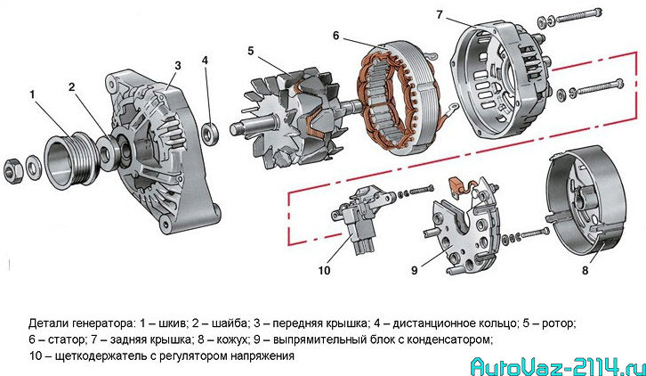
What is a generator
Can be represented as an electric three-phase machine alternating current. It has a built-in rectifier unit that converts AC to DC. The device consists of the following parts:
- Aluminum alloy front and back cover. Each of them has sockets for installing bearings. On the body of the back cover there is a terminal connector for supplying voltage to the excitation winding. A capacitor is also installed on the back cover, which suppresses radio interference, there is a place for installing and attaching the brush assembly;
- Stator core cylinder made of transformer iron. Inside it there are grooves for laying the power windings of the generator. They have leads for connection to the rectifier unit. Both covers are attracted to the stator with four bolts;
- Excitation winding on the rotor shaft. With its conclusions, it is connected to slip rings made of copper, which are installed on the same shaft. The front of the shaft has a keyway for mounting the drive pulley;
- Generator brushes are a non-separable unit, combined with an electronic relay-regulator. metal case riveted to the brush holder;
- A block of power and additional diodes is attached to the back cover from the inside. It consists of six power and three additional diodes. To cool semiconductor devices, they are mounted on horseshoe-shaped aluminum alloy plates.
Some of its specifications
The generator set provides the following parameters:
- The excitation winding is powered by an adjustable voltage from 13.2V to 14.7V;
- The current generated by the voltage generator is 80 A;
- The deflection of the belt must not exceed 8 mm with a load of 10 kg.
The generator is mounted on the engine on its left side in the direction of the machine. The rotation of the rotor is right, which it receives with the help of a drive belt from crankshaft motor.
Generator breakdowns
It can be conditionally divided into "mechanical" and "electrical". Let's look at them in that order.
Malfunctions from the category "mechanical"
An indirect confirmation of the presence of such a breakdown is the increased noise of the generator set during. It can "make noise" in some other cases, but this will be discussed a little later. The source of increased noise in most cases is worn out. First of all, this concerns the bearing in the front cover of the generator. It experiences increased radial loads, so it can fail faster . Over tensioning the drive belt will increase the load on the bearing.
Malfunctions from the category "electrical"
There may be several, these are:
- Lack of battery charge voltage;
- The generator produces low voltage;
- Over charge voltage.
The generator set can be carried out without removing it from the machine. To do this, you need to have a measuring device such as a tester, multimeter or voltmeter direct current. Even a simple Chinese tester will do. By measuring the voltage at the battery terminals, we can draw a definite conclusion about the performance of the generator.
The method of checking the generator, in which the positive terminal is removed from the battery, cannot be used, in order to avoid failure of the electronic relay-regulator or other vehicle electronics. We will consider more specific verification methods a little later. Now let's remember how to remove the VAZ 2114 generator for further verification.
How to remove the generator from the car
It is installed in a special bracket on the cylinder block, there is also a bar for tensioning the alternator belt. Find the generator in front of the engine compartment on the right side in the direction of the car. For removal, you need to prepare the following tools:
- Wrench on "10";
- The same key on "13"
- Open-end wrench 17x19;
- Head on "15"
- Mount.

Removal is carried out in several ways, where it is required to remove the engine protection. They are well described in various sources. Let's try to remove it without removing the protection. The procedure will be as follows:
- The first step is to disconnect the terminals from the battery;
- Weaken the belt tension, first remove the belt, and then the entire tension mechanism;
- battery, they are covered with a rubber cover, and a connector for supplying voltage to the excitation winding;
- The generator on the bracket is mounted on a long bolt with a nut. It is not very convenient to get it, therefore, with the head on “15”, two bolts securing the bracket to the block are unscrewed. They are found at the back of the generator, one bolt is long and the other is shorter. Now the generator can be turned clockwise and it will be possible to remove the axis of its attachment to the bracket;
- Unscrew the nut with a key to “19” and remove it together with the remote sleeve;
With a small punch or something similar, the axle is knocked out of the bracket. The generator is pulled up. Now you can carry out generator repair or maintenance with it.
How to disassemble VAZ 2114 generators
To perform the work, you need an open-end wrench for "10", "19" and a Phillips screwdriver.
Disassembly of the VAZ 2114 generator is carried out in the following order:
- Press three latches and remove the plastic protective cover on the body;
- Mark the relative position of the covers and the stator, to facilitate subsequent assembly;
- With a screwdriver, unscrew the screws securing the brush assembly, remove it from the housing;
- Disconnect the wires from the output of the regulator;
- Unscrew the four screws securing the rectifier unit, disconnect the winding leads and remove it together with the noise suppression capacitor;
- Turn out four coupling screws, which are tightened during assembly with great effort, and remove the cover from the side of the slip rings of the generator;
- The rotor shaft is clamped in a vice so that it cannot turn, and the nut securing the pulley is unscrewed. Now you can remove the alternator pulley and thrust washer from the rotor shaft;
- Remove the cover from the generator rotor.
After that, you can carefully inspect all parts for wear or damage.
Symptoms of Generator Set Problems
Brush assembly malfunctions
This node may have problems with electronic regulator and brushes. Replacement of brushes of the generator can be made without its removal from the engine. It is impossible to check this block without removing it from the generator, therefore, if there is such an opportunity, then you can simply change the brushes. You can check its operation, there is an adjustable power supply and a control light. Connect the power to the "+" and "-" of the regulator, and the light bulb to the brush. It should glow, and when the input voltage increases to 15-16 volts, the light goes out. If this does not happen, then the tablet needs to be replaced. Let's look at the signs of brush wear. This will be evidenced by:
- Low onboard voltage;
- Lack of battery charging;
- Charging voltage spikes.
Brushes in a free state must have a length of at least 0.5 cm. If they are shorter, they are completely replaced. brushes and their free movement in the grooves. If there is a hang, it can be eliminated with a drop of oil in the grooves. Check the slip rings, their surface, for wear. If available, sand the surface of the rings with a fine sandpaper. When the brushes of the VAZ 2114 generator are replaced, the performance will be restored in a few minutes, after rubbing the brushes and slip rings.

Diode bridge and its problems
Symptoms of a malfunctioning generator diode bridge can be as follows:
- Complete lack of charging;
- The charging voltage is much higher than normal.
All this can cause great negative consequences for the entire electrical system of the car. hands is possible, but subject to the availability of experience and instruments for working with electrical equipment. For example, signs of a breakdown of a diode bridge have been identified, and its repair is required.
Most often, in this case, a breakdown of the horseshoe power diodes occurs. It is not very difficult to replace them, the problem is that they are not in spare parts. You can look for repairmen who repair electrical equipment of cars. It will be easier and cheaper to purchase a new unit with a diode bridge, and replace it with a failed one. The diode bridge is replaced in the following order:
- A contact bolt with insulating bushings and nuts is mounted in the block and clamped;
- Correct and install the leads of the stator windings and tighten the nuts at the points of their connection;
- Replace the bolts securing the rectifier unit and tighten them;
- Install the brush assembly with the regulator in its place, and fix it with screws on the back cover case;
- Install a protective cover made of plastic and fix with three clamps.
After that, the device can be mounted on the installation site, connect the wires, put on and tighten the drive belt, and you can check its operation.

About replacing a generator set on a vehicle
It so happened that the replacement of the VAZ generator is necessary. The required spare part has been purchased. By the way, some motorists are replacing serviceable nodes with more powerful installations. The reasons for this can be very different. Basically, this is the installation of new, additional consumers of electricity. Powerful audio systems, good headlights, body kit lighting and other similar “things” require an increase in the power of the generator set.
In such cases, they usually purchase and install a generator from Priora or Kalina. Its generated current is approximately 115 A, while the standard device produces 80 A. Its fastening is similar to the standard one, only it is necessary to replace the drive belt pulley. The case is not very difficult, even inexperienced drivers can cope with it.
Required tool to replace alternators:
- Wrenches for "10", "13";
- Open-end wrench 17x19;
- Screwdriver Set;
- Mount.
Replacement work begins only after the battery is disconnected.
If the work is done in a garage with a viewing hole, then the following procedure can be recommended:
- Disconnect the engine protection. You can release it only in the area of the generator set and leave it in limbo;
- With a “10” wrench, twist the nut on the protruding contact bolt of the generator and remove the wires from it. Also disconnect the connector from the brush assembly;
- Unscrew the bolt of the tensioner, the bolt of its fastening to the cylinder block and remove it from the engine;
- Now the nut of the axis of the bracket for mounting the generator is unscrewed. This action is performed with a key to "19", remove the nut with a distance washer and knock the axle out of the bracket.
The generator can be removed from the engine compartment and a new one installed in its place. Installation is carried out in the reverse order. Connect previously disconnected wires and connectors, put the drive belt in place. After that, it can be tested in work. Before starting the motor for testing, a few words about how to do it right. This process is somewhat different for different engine displacements. With a volume of 1.5 liters, the belt is tensioned by moving the generator housing away from the engine block with a mount. With a volume of 1.6 liters, tighten the belt with a tensioner screw.
Take care of your car!
The main sources of electricity in a car are the battery and the generator set. The article discusses the VAZ 2114 generator: a device, possible faults, methods for their elimination, instructions for removal are given, photo and video materials are attached.
How is a generator set up?
The generator on the VAZ 2114 is a three-phase device. Its task is to convert AC to DC.

The design of the unit consists of the following elements:
- Front and rear aluminum covers, on each of which bearings are mounted. The rear cover is equipped with a terminal for connecting power from the battery and a connector for supplying current to the excitation winding. In addition, a capacitor is installed on the back cover, designed to suppress radio interference, and a brush assembly is also attached.
- Stator. Its core cylinder is a set of plates that are made of special transformer steel. The power windings of the generator set are placed in the stator slots, which have leads for connection to the diode bridge. Both covers are attached to the stator with 4 bolts.
- Rotor. The conclusions of its excitation winding, which is located on the shaft, are connected to slip rings located on the same shaft. In front of the rotor there is a keyway in which the VAZ 2114 generator drive pulley is attached.
- On the VAZ 2114 there is a three-level voltage regulator, which is combined with a brush assembly, which is a non-separable device. The relay-regulator is located in a metal case. The brushes transmit voltage from the regulator to the rotor winding.
- A diode block is attached to the inside of the back cover, in which there are nine diodes. Of these, six main and three additional. In order for the semiconductors to cool sufficiently, they were placed on an aluminum plate in the form of a horseshoe.

VAZ 2114 generator - device
The operation of the generator set is carried out due to the fact that in stator winding there is an electromotive force, which is created due to rotation magnetic field rotor.
Technical characteristics of the generator set:
- the excitation winding requires an adjustable voltage ranging from 13.2 to 14.7 V;
- the generator generates a current of 80 A;
- with a load of 10 kg, the deflection of the drive belt should not be more than 8 mm.
The generator set is located on the left side of the engine. A right-hand rotor is installed, which is carried out thanks to a belt drive from the engine crankshaft.
Possible malfunctions: signs and causes
The generator set is an electromechanical device. Therefore, two types of faults are possible: mechanical and electrical.
A sign of the appearance of mechanical problems is increased noise that is heard during the operation of the generator. The cause of the noise is the destruction of the bearing pressed into the cover. It constantly experiences large radial loads, so it has a short service life.
The overstretched VAZ 2114 reduces its service life. Therefore, it is necessary to monitor its tension and condition. The generator will not run if the belt breaks.
Signs of electrical problems are:
- the generator does not charge the battery;
- charging voltage is too low;
- charging voltage is too high;
- the unit is heating up.
You can determine the malfunction using a multimeter. You can judge an insufficient charge by weakly burning headlights and slowly working wipers, as well as by a control light that blinks or is constantly on. If the charge is too high, then the electrolyte in the battery boils, and the headlights shine too brightly.
Node diagnostics
The generation of insufficient charge by the generator set leads to the fact that the incoming voltage is not enough to power all electrical equipment. In this case, the battery comes to the rescue. As a result, it can be completely discharged. Too high voltage is even more dangerous for the on-board network, as it can blow fuses and burn out electrical components.
Knowing what voltage the VAZ 2114 generator should produce, you can diagnose it to identify malfunctions (the author of the video is Ildar Latypov).
Diagnostics is performed using a multimeter set to voltage measurement mode.
Checking the VAZ 2114 generator consists of a sequence of actions:
- First you need to turn on the ignition and start the engine.
- If there is damage in the rotor winding circuit, then the warning light on the instrument panel will be constantly on.
- The power unit should be warmed up to about 90 degrees. The crankshaft speed should be about 2500-3000 rpm.
- Then you should turn on the dipped beam and radio.
- Now you need to measure the voltage that is supplied to the battery terminals. It should be around 13V.
- Turning off the radio and turning off the low beam, again measure the voltage. It should increase to 14.7 V.
During diagnostics, you should listen to the operation of the rotor. If the bearing in the front cover fails, noise will be heard.
Voltage drop is possible for the following reasons:
- weakening the tension of the alternator belt;
- brush wear;
- malfunction of the relay-regulator;
- wear of the entire generator set.
If the generator unit is completely worn out, it must be completely replaced. Before changing the generator to a VAZ 2114, you should perform its diagnostics. If not, the cause may be a broken belt.
Unit Removal Guide
If the bearing is destroyed, it is necessary, and for this you will have to dismantle it. The generator set is attached to the engine block on a special bracket. There is also a strap for adjusting the belt tension.

To remove the generator set on the VAZ 2114, you need to stock up on the following tools:
- a set of wrenches, preferably both cap and open-end wrenches;
- socket head on "15";
- mount, or a piece of metal pipe.
Possible options for dismantling the generator set with the removal of protection power unit and without. We will consider the option without dismantling the protection. Before removing the generator set, you must disconnect the negative terminal on the battery to avoid a short circuit.
The procedure consists of the following steps:
- First, using the key on "17", you need to loosen the tension of the alternator belt. To do this, unscrew the fastening nut from above and move the unit to the cylinder block.
- Next, on the output bolt “31”, it is necessary to unscrew the nut and disconnect the supply wire that goes to the excitation winding of the rotor.
- From below, the generator is attached with a nut and a long bolt, they need to be unscrewed.
- To make it more convenient to get the generator, you need to unscrew the bar with which the assembly is attached to the engine block. To do this, unscrew the two bolts.
- You should also carefully unscrew the nut securing the strap to the starter. If the fastener is stuck, you can use a penetrating lubricant, which makes it possible to remove rust and dirt.
- To remove the axis of fastening the generator to the bracket, it is better to turn it clockwise.
- Next, use the key to "19" to unscrew the nut and remove it and the remote sleeve.
- Now the generator unit can be removed upwards.
With the option of dismantling the generator through the bottom, you need to remove the protection.
How to troubleshoot the generator of the fourteenth VAZ model?
Troubleshooting depends on the causes that caused them:
- If the fuse is blown, it must be replaced. All fuses are in mounting block. A blown fuse indicates a fault in the circuit. It needs to be checked, the exact cause found and eliminated.
- If there is no power, check the reliability of the fastening of the negative wires.
- If there is a problem in the ignition switch, you need to check contact group. If it was not possible to restore the lock to working capacity, it should be completely replaced.
- To determine the problems that have arisen in the power circuit of the rotor winding, a control light is provided. If it's burned out, it needs to be replaced.
- The replacement of the generator brushes is carried out together with the voltage regulator relay. Separately, the regulator is not repaired.
- The generator does not charge due to a broken drive belt, a new consumable is installed. In this case, the size of the belt must be appropriate so that the tension is sufficient. Replacing the alternator belt VAZ 2114 8 valves and 16 is similar.
- If the voltage of the on-board network is low due to a weak belt tension, the tension must be adjusted.
- If a rumble and crackle is heard in the front cover of the generator, the bearing is replaced, since it is most often the cause of noise.
Photo gallery
 1. Complete generator set
  2. Disassembly of the assembly
  3. Diode bridge
  4. Brush assembly
Conclusion
Repair of the VAZ 2114 generator depends on the detected malfunctions. Knowing how to check the generator, you can detect its malfunctions. Some of them do not even require the removal of the generator. For example, the alternator gives a weak charge or does not charge - the reasons are a weak tension or a broken drive belt.
If the bearings are destroyed, the assembly will have to be almost completely disassembled. Disassembly of the generator will be required when replacing the diode bridge.
It is important to determine the exact cause of the failure in order to restore the generator set to service.
This video demonstrates how to dismantle the VAZ 2114 generator set without removing the protection from the motor (the author of the video is fedot580).