The content of the article:
Each element that makes up an internal combustion engine is an integral part of the system, on which the quality of operation of the entire mechanism depends. One of the most expensive and significant design elements of a diesel engine is the crankshaft. It will perform the most important function, which is to facilitate the conversion of the forward-return dynamics of the pistons into torque. In addition, this mechanism responds to variable influences of gas pressure that arise from time to time, and to the influence of inertial forces of masses in motion.
An automobile crankshaft is a complete system, so it can be called a part. This part is made from high quality durable steel. Production method: forging. Sometimes cast iron is used as the main production material; in this case, production is carried out by casting. Diesel and turbocharged engines use the most durable and durable steel crankshafts.
Video about how a crankshaft is made:
Crankshaft device
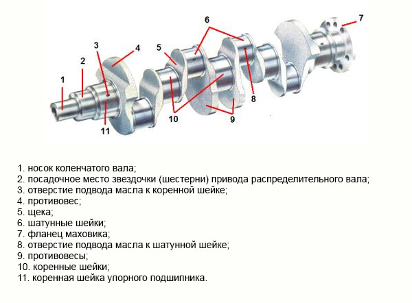
The photo shows the diagram crankshaft
The system of the engine part in question includes main and connecting rod journals, which are connected to each other by cheeks. As for the number of journals, the number of main ones, as a rule, exceeds the connecting rods by one unit. Such shafts are called full-support shafts. The connecting rod journals have a smaller diameter compared to the main journals. A counterweight is installed in the direction opposite to the location of the connecting rod journal. This element contributes to the balance of the pistons and connecting rods. Its functioning is very important as it ensures that the entire engine runs smoothly.
The connecting rod journals are located between the two cheeks. Their name is knee. The knees are installed based on the number, method of operation and location of the cylinders, as well as the dynamics of the engine. The main task of the knees is to maintain the balance of the internal combustion engine, uniform ignition, and minimize vibrations and bending moments. In addition, an important function of the crankpin is to support the connecting rod.
In the crankshaft device system, the area where the shaft journal passes to the cheek has the highest degree of load. In order to keep the stress concentration at a low level, this junction is installed with a fillet (radius of curvature). The fillet system helps elongate the crankshaft.
Sliding bearings, which are an integral part of the shaft, contribute to rotational movements shaft in supports and connecting rods in journals. The bearings are liners with thin walls. They are made from high-quality steel tape, onto the surface of which an anti-friction solution is applied.
To prevent rotation of the liners near the neck, a protrusion is installed that fixes their location in the support. And in order to avoid axial dynamics of the crankshaft, a plain bearing is used. It is installed on the molar neck (extreme or inner middle).
Crankshaft lubrication system design
The DVZ lubrication system includes both connecting rod and main journals. They are lubricated under pressure. The common oil supply line to the engine elements supplies it to each journal support. After this, oil is supplied to the connecting rod journals.
Power from the crankshaft is taken from its shank ( reverse). At the end of the front part of the shaft, places are installed where the shaft drive gear, pulley and torsional vibration damper are secured. IN general view they are two disks connected by a material with a high degree of elasticity (rubber, spring part, liquid silicone). These substances are able to absorb vibrations of the shaft, causing friction inside it.

The photo shows a diagram of the crankshaft lubrication system
Video about the working principle of the crankshaft:
The crankshaft is an important part because it converts the reciprocating movements of the pistons into torque. Crank device the shaft is as follows: cheeks, connecting rod and main journals, counterweights, shank, flange.
Support - root necks. Classic four-cylinder engines have five-bearing crankshafts. The design of three supports is rarely used, because it is not so durable. Seven-bearing shafts have six-cylinder engines. Typically, small bore cylinder blocks use single counterweight crankshafts. During manufacturing and repair, the surface of the main and connecting rod journals is carefully polished.
Types of crankshafts
There are crankshafts with and without double counterweights.. The crankshaft must be wear-resistant, low weight, balanced, and precision machined. Crankshafts are made from high-strength alloy steel. There are also cast crankshafts made of high-strength cast iron, which are hardened by high-frequency currents. There are also hollow crankshafts.
How does a crankshaft work?
The crankshaft is subject to bending and twisting forces during operation. To avoid premature destruction, the interface between the connecting rod journals and cheeks is made slightly rounded. If the engine is running normally, the crankshaft main and connecting rod journals gradually wear out, just as when the bearings slide.
A thin oil film is created due to the supply of oil under pressure. After some time, the gap between the liner and the neck will become larger, the pressure will decrease and the quality of the oil film will decrease. Wear increases, the neck touches the liner with great force, the pressure decreases again and now work is impossible, because due to excessive friction the temperature rises, the neck engages with the liner and it rotates.
You can check whether the crankshaft journals are worn using the oil pressure in the oil line at maximum and minimum speeds of a warm engine. You can measure the gap between the journals and bearings on a disassembled engine using a plastic wire. The smaller the gap, the greater the deformation. Depending on the engine design, a pulley, a torsional vibration damper, a camshaft drive sprocket, auxiliary and balancer shafts are installed on the crankshaft shank.
The design of the crankshaft and its operating principle.
The crankshaft's job is to convert the reciprocating motion of the internal combustion engine pistons into torque. The crankshaft receives periodic variable loads from gas pressure forces and inertial forces of moving and rotating masses. It is an integral part of the crank mechanism (CCM) and one of the most expensive and important structural elements of the engine.
Most often, the crankshaft is a one-piece structural element - they are non-separable. There are exceptions - collapsible crankshafts, which are used on motorcycles, motorcycles, ATVs, etc. Cars are equipped with non-separable crankshafts, which cannot be repaired after cracks or breakage occur.
For this reason, the popularity of contract (used) crankshafts from Japan, Europe, and America is high. When purchasing a crankshaft from a car disassembly site, it is usually supplied with bearings removed directly from the vehicle being disassembled. In this case, the question “will it fit or not” is not asked; it is also important that when purchasing a used one. spare part, you are buying 100% original. You can, of course, purchase an original new crankshaft, but its price will be several times higher than that of a contract one. So, for example, used A crankshaft for a Honda Civic can be bought for 2,000 rubles, and the cost of a new one starts from 15,000 rubles.
However, such types of crankshaft repair as balancing, straightening, restoration of the mechanically deformed surface of the journals (restoration of raised crankshaft journals) are common.
Let's look at how the crankshaft works. It consists of a series of connecting rod and main journals connected by cheeks. The most popular type of crankshaft is a full-support one, which has one more main journal. The connecting rod journals have a smaller diameter than the main journals. A counterweight in the crankshaft ensures smooth engine operation by balancing the weight of the pistons and connecting rods. The crank is the connecting rod neck located between the two cheeks. How many elbows are in the crankshaft and how they are placed depends on the operating principle of the engine cylinders, as well as its clock cycle. The connecting rod journal acts as a support for the connecting rods.
Since the transition from the neck to the cheek is loaded, to reduce the load, the transition from the neck to the cheek is performed with a radius of curvature. This radius is called a fillet. Since fillets significantly lengthen the crankshaft, they are produced with a recess into the neck or cheek.
To ensure rotation of the connecting rods in the connecting rod journals and the crankshaft in the supports, plain bearings are used. There is an individual oil supply to each of the main journal supports, then the oil is supplied through channels in the cheeks to the connecting rod journals.
Power is taken from the crankshaft from the shank on which the flywheel is mounted. Seats are located at the front end of the crankshaft. The following are attached to them: a drive pulley for auxiliary units, a camshaft drive gear, and a torsional vibration damper. Traditionally, the crankshaft is made of steel (for diesel and turbocharged engines) or cast iron.

The crankshaft is located in the engine cylinder block and allows you to convert the reciprocating movement of the pistons with connecting rods into rotation. This rotation is transmitted through the transmission to the drive wheels of the car.
The crankshaft is made by forging from high-alloy steel, or by casting from high-strength cast iron, followed by hardening and machining. Since it transmits serious moments, the requirements for bending and torsional strength of the crankshaft are very high.
How the crankshaft works
The crankshaft is a crank. Hence the name “crank mechanism”. It includes the crankshaft along with the pistons, their rings, pins and connecting rods. As well as a flywheel with a crown and a pulley for driving auxiliary mechanisms.
From the name it is clear that the shaft is not straight, but has structural elements such as elbows. They are called connecting rod journals.
- In in-line engines, their number is equal to the number of cylinders - each piston with connecting rod acts on its own journal.
- In V-twin and boxer engines, one crankpin may be designed to carry the load of two connecting rods with pistons from adjacent cylinder banks.
The center of rotation of the crankshaft is the main journals. Between the main and connecting rod journals there are cheeks on which elements called counterweights are made. The transition from each neck to the cheek is not made at a right angle, but has a radius - a fillet. The fillet is needed to prevent the occurrence of fatigue cracks, since in this place of the shaft there is the highest concentration of metal stress.
- The main journals have a larger diameter than the connecting rod journals. The connecting rod journals alternate with the main ones, and the number of the latter is greater—a full-support crankshaft.
- Crankshafts that do not have main journals on both sides of the connecting rods are not fully supported, and have almost never been used recently. This is due to increased requirements for crankshaft rigidity due to the increased compression ratio of modern engines.
Liners are used as bearings in which the crankshaft journals rotate. The bushings are plain bearings. They are made of a steel strip bent along the radius of the crankshaft journal and coated with a thin layer of aluminum alloy or bronze, which has a low coefficient of friction. The inserts have locks to prevent them from turning in their pastels.
There is a gap between the crankshaft journal and the surface of the liner. When the engine is running, there is always an oil film in this gap - an oil wedge. Essentially, the crankshaft rotates on this oil wedge rather than on a bearing.
To supply oil to the contact points of the journals and bearings, the crankshaft has oil channels connected to the main oil line and the oil pump.
For two-stroke motorcycle engines, as well as industrial and agricultural diesel engines with large cylinder displacements, the following can be used as bearings for crankshafts:
- ball bearings;
- roller bearings;
- needle roller bearings.
To transmit torque to the transmission, a flywheel is bolted to the rear end of the crankshaft. Due to its large weight and inertia, it smoothes out shocks from the pistons during their working stroke.
Recently, dual-mass flywheels have become widespread, also acting as a torsional vibration damper.
In transmissions with mechanical boxes gears, the flywheel is the driving clutch disc. In transmissions with automatic transmissions gears, the torque converter pump wheel housing is attached to the flywheel.
At the front end of the crankshaft, as a rule, on a keyed connection, a gear is attached - a timing pulley and an auxiliary drive pulley.
Due to the global tendency of the engine industry to reduce the weight and size of parts of the crank mechanism, as well as to increase the nominal speed and compression ratio of engines, the problem of the occurrence of resonant vibrations has arisen, leading to breakage of the crankshafts. To eliminate this, dampers were built into the crankshaft pulleys to dampen torsional vibrations. As already noted, dual-mass flywheels are aimed at this.
Crankshaft faults
The main malfunctions of crankshafts include:
- wear of the journals, their fusion with the antifriction coating of the liners;
- cracks in the necks;
- crankshaft bend;
- broken cheeks.
The most common malfunction is wear of the journals. A sign of extreme wear of the crankpins of the crankshaft and their bearings is a metallic knock, the frequency of which is half the crankshaft rotation speed. After the engine warms up and under load, the knocking intensifies. If you turn off the injector, or the voltage supply to the spark plug in the cylinder, the connecting rod of which interacts with the worn journal, the knocking noise decreases significantly or disappears completely.
A dull metallic knock equal to the crankshaft rotation speed, which intensifies under load and after the engine warms up, is a sign of emergency wear of the main journals and their bearings. Such a knock may also indicate deformation of the crankshaft due to overheating of the journals when the liners are destroyed.
Reduced pressure in the lubrication system, especially at Idling a warm engine and a knock that quickly disappears after starting the engine are also indirect signs of wear on the crankshaft bearings and journals. If the crankshaft cheek breaks near the main journal, a metallic knock will also be heard, a multiple of the shaft revolutions.
Cracks in the journals are detected when the crankshaft is removed from the engine.
Consequences of using a faulty crankshaft
If you continue to operate the engine with obvious signs of severe wear on the crankshaft, the consequences of such operation may be:
- failure of the oil wedge in the liner-neck pair;
- dry friction;
- overheating and fusion of the journal with the aluminum coating of the liners and subsequent jamming of the crankshaft.
If all this happens at high speeds, then rotation of the liners in their pastels, followed by expensive repairs of these pastels, or replacement of the cylinder block and connecting rods, is also very likely.
The consequences of operating an engine whose crankshaft has cracks can also be its breakdown and deformation of the pastel liners in the block.
After a knocking engine is jammed, there is no need to try to turn its crankshaft with a large crank or with a tow. The consequence of this will certainly be the rotation of the liners, welded to the HF necks, in their pastels.
How to install the crankshaft correctly
When you independently “install” the crankshaft into the engine of your car, you need to remember simple rules:
- There must be a gap between the surfaces of the crankshaft journals and the bearings for the oil wedge. The size of this gap is set by the manufacturer of a particular motor. The gap should not exceed these tolerances;
- the crankshaft, its channels, cylinder block, liners and the assembler’s hands must be perfectly clean;
- The diameter of the crankshaft journals must correspond to the factory tolerances and dimensions of the liners. It is impossible to use inserts of repair sizes with journals of nominal size and vice versa. With a nominal size crankshaft, use only nominal bearings. If the crankshaft journals are ground to the repair size, then the liners must be used according to the repair.
- Before placing the crankshaft in the cylinder block, you need to ensure the quality of the connecting rod bearings and the connecting rods themselves. If, before repair, some of the connecting rods were damaged or the bearings were turned, you need to tighten the connecting rod cap to the torque prescribed by the manufacturer and check the inner diameter of the lower head of the connecting rod for compliance with the factory dimensions. If these dimensions do not correspond, replace the connecting rod.
If everything is in order with the connecting rod, you need to insert the liners into the connecting rods, lubricate them with oil, preferably transmission oil, and tighten to the specified torque. Each on its own crankpin. After turning the connecting rod several turns around the neck, remove it and check the surface of the liners. They should not show any marks from contact with the crankpin. If there are traces of contact and the connecting rod is difficult to rotate around the journal, the liner will have to be replaced.
It must be remembered that at the factory the cover was bored together with its connecting rod, in a position where the grooves for the liner locks are on one side. Therefore, caps and connecting rods cannot be confused with each other. When installing the cover on the connecting rod, the locks of the liners should be on one side.
Having checked the connecting rods and their bearings, we proceed to laying the crankshaft into the cylinder block. The requirements for the pastels of the main liners in the cylinder block are the same as for the connecting rods. In addition, the pastels in the engine block must be strictly pine. Light alloy cylinder blocks are especially susceptible to misalignment and wear of pastels.
If everything is in order with the size and alignment of the pastels, we insert inserts into them. As a rule, the main liners inserted into the cylinder block have a groove in the middle for better oil supply, and the liners in the covers, which bear the main load when the engine is running, are solid. They must not be confused during assembly.
Having installed the thrust rings in your pastels, lubricate the bearings with oil and place the crankshaft in them. We install the main bearing caps in place and tighten them to the specified torque. We start tightening from the middle lid to the outer ones, in a checkerboard pattern.
The covers should not be confused with each other, since the holes for the crankshaft in the cylinder block are bored in one pass, with the cover mounting bolts tightened. In this case, the grooves for the locks of the liners in the pastel of the cylinder block and its cover are located on one side. They should be installed in this position when assembling the crankshaft with the block.
After tightening all the caps, turn the crankshaft a few turns. It should turn freely by hand without jamming. We measure the axial clearance between the thrust half-rings and the cheek and remove the crankshaft.
We inspect all the inserts. There should be no traces of contact with the necks. If this is the case and the measured axial clearance of the thrust half-rings corresponds to the norm, we finally place the crankshaft in the cylinder block and tighten its covers from the center to the extreme torque.
If some liners are pinched, but the geometry of the crankshaft and cylinder block pastels are all right, such liners will have to be replaced.
That's all about the crankshaft.
This is the heart of any modern car.
This unit consists of several main elements:
- cylinders;
- pistons;
- crankshaft;
- flywheel.
Together they form a crank mechanism. The crank, also known as the crankshaft (Crank Shaft) or simply the crankshaft, performs a very important function - it converts the translational motion created by the pistons into. When the needle on the tachometer approaches 2000 rpm, this indicates that the crankshaft is making exactly that number of revolutions. Well, then this moment is transmitted through the clutch to the transmission, and from it to the wheels.
Device
As you know, pistons in an engine move unevenly - some are at top dead center, others at bottom. The pistons are connected to the crankshaft using connecting rods. To ensure such uneven movement of the pistons, the crankshaft, unlike all other shafts in the car - primary, secondary, steering, gas distribution - has a special curved shape. That's why it's called a crank.
Essential elements:
- main journals - located along the axis of the shaft, they do not move during rotation and are located in the engine crankcase;
- connecting rod journals - offset from the central axis and during rotation describe a circle, it is towards them that connecting rod bearings connecting rods are attached;
- shank - the flywheel is attached to it;
- sock - a ratchet is attached to it, with which the timing drive pulley is screwed - the generator belt is put on the pulley, which, depending on the model, also drives the blades of the power steering pump and air conditioning fan to rotate.
Counterweights also play an important role - thanks to them, the shaft can rotate by inertia. In addition, oil nipples are drilled into the connecting rod journals - oil channels through which engine oil flows to lubricate the bearings. The crankshaft is mounted in the engine block using main bearings.
Previously, prefabricated crankshafts were often used, but they were abandoned because due to the intense rotation at the joints components Huge loads arise and not a single fastener can withstand them. Therefore, today they mainly use full-support options, that is, cut from one piece of metal.
The process of their production is quite complex, because it is necessary to ensure microscopic precision, on which the performance of the engine will depend. During production, complex computer programs and laser measuring equipment are used that can determine deviations literally at the level of hundredths of a millimeter. Also of great importance is the accurate calculation of the mass of the crankshaft - it is measured down to the last milligram.

If we describe the principle of operation of the crankshaft, then it fully corresponds to the valve timing and operating cycles of a 4-stroke internal combustion engine, which we have previously described on the site. That is, when the piston is at the top point, the connecting rod journal articulated with it is also located above the central axis of the shaft, and as the shaft rotates, all 3-4, or even 16 pistons move. Accordingly, the more cylinders in the engine, the more intricate the shape of the crank.
It is difficult to imagine what size the crankshaft is in the engine of mining dump trucks, which we also talked about on our website. For example, the BelAZ 75600 has an engine with a volume of 77 liters and a power of 3500 hp. A powerful crankshaft drives 18 pistons.

Crankshaft grinding
The crankshaft is a very expensive thing, however, due to friction, it becomes unusable over time. In order not to buy a new one, they polish it. This work can only be performed by highly qualified turners who have the appropriate equipment.
You will also need to purchase a set of repair connecting rod and main bearings. Inserts are sold in almost any spare parts store and go under the designations:
- N (nominal size) - correspond to the parameters of the new crank;
- P (P1, P2, P3) - repair inserts, their diameter is several millimeters larger.
Based on the size of the repair liners, the machinist accurately measures the diameter of the journals and adjusts them to the new liners. For each model, the pitch of the repair inserts is determined.

You can extend the service life of the crankshaft by using high-quality motor oil and its timely replacement.