Domestic cars can be repaired independently in any convenient garage. Their design provides for the maximum level of maintainability of all components and mechanisms. No exception in this case will be the repair of the cylinder head; one of the operations of this process is the replacement of valve guides.
In progress valve mechanism valve movement occurs in a limited space. The direction for movement is set using the coaxiality of the hole in which the axis of the rod and the inlet/outlet “walks”. The material for the rod is selected to be as wear-resistant as possible.
The steel is alloyed with large amounts of chromium and nickel. The valve guides mating with the stem are made of less durable material, often copper-containing alloys. This is due to the fact that a repair kit of such bushings will cost less to maintain than a complete replacement of valves with a worn stem. Also, the steel-brass pair works much better with frictional mating.
Replacing bushings
There is practically no gap between the hole and the valve. This and the presence of seals on the rod help prevent oil from entering the combustion chamber. But due to the fact that the valves operate under aggressive conditions and with intense movement, the bushings wear out and they have to be changed periodically. If they were not included in the structure, then the entire head of the blocks would have to be replaced after they were worn out in the holes along which the rod runs.
The need to replace bushings
Wear can be determined by several indirect signs; there are also cases when it is necessary to change bushings:
- into the combustion chamber engine oil penetrates, due to this, its consumption increases and grayish smoke is formed from the exhaust pipe;
- a characteristic tapping sound is heard from the side of the block head;
- at complete replacement of the kit valves;
- overhaul block heads.

Pressing tool
Pressing out bushings
The most popular pressing method is impact. We clean the previously removed block head from dirt. Then we fix it on the workbench. For the operation you will need a special puller, a brass or bronze cylindrical mandrel 80-100 mm long. At one end there should be a groove 30-40 mm long with a diameter 1-2 mm less than the diameter of the inner hole of the sleeve.
The mandrel must have a maximum diameter no larger than the outer size of the sleeve. Before knocking out the bushings, it is necessary to heat the head to approximately 100-120 C
. This is done to loosen the tension between the bushings and the body. In garage conditions, an electric stove is suitable. Under no circumstances should you use a torch for this operation, so as not to overheat the metal and spoil the “geometry” of the surface of the body part. It must be knocked out from the side of the combustion chamber. After releasing the mounting hole, you need to measure its diameter. This is necessary in order to correctly select the interference, the difference between the size of the new bushing and the landing diameter. The repair sleeve should be 0.03-0.05 mm larger.
This will ensure a tight fit. Measurements should be taken on a cooled head.
Pressing in the repair kit
To avoid damaging the surface of the holes and creating scuffing, before replacing the valve guides, you need to warm up the cylinder head a little again. The repair kit needs to be cooled for a better fit. A household freezer is suitable for this. Without such manipulations, high-quality pressing may not be achieved, and subsequently they will all quickly “loose” in their places. And it will be necessary to disassemble the assembly again.
Mechanism assembly When everything is in place and the block head has cooled down to ambient temperature, It will be necessary to process the holes with a reamer.
This calibration will bring the diameter to the desired size along the entire length. It is advisable to use an adjustable tool, since a non-adjustable tool wears out and the hole size will become slightly smaller than required after a large number of treatments. Due to this, the valves will move with tension, overcoming friction, or they may simply jam.
The normal gap between the valve stem and the hole is 0.03-0.04 mm.
After pressing the bushings, the valve seats can be adjusted. For this operation, cutters or countersinks are used.
Valve guides, what they should be, their installation clearances, and more. Greetings to all lovers engine, your motorcycle or car. In this article we will talk about fairly small but important parts of any engine - valve guides. Despite its modest size, the valve guide bushing is a very important part, and sooner or later every experienced driver begins to take an interest in it, even those who take their engine to a car repair shop for repairs.
The guide bushings of any engine provide precise direction to the reciprocating movement of the valves, for their opening and closing at the right moment, and the flow rate, as well as the tight and precise fit of the valve plate to its seat, directly depends on the state of the rubbing bushing-valve pair. In addition, the guide bushing is a part through which heat is transferred from the valve stem to the engine head. Heat is also transferred to the engine head through the valve plate and seat (when the valve is closed).
The appearance at one time of valve seats and guides served as an impetus for replacing the ever-overheating cast-iron engine heads with more advanced aluminum heads that dissipate heat better and cool faster.
Indeed, at a time when the heads were cast iron, there were no guide bushings and valve seats, that is, these parts were one with the cast iron body of the head. And when the guide holes along which the valve stems slid were worn out, as well as when the seat of the valve plate was worn out (or burned out), the cast-iron head had to be replaced with a new one.
But on the other hand, every design decision of the engine head can come from many reasons. After all, the processes of heat removal from the valve into a monolithic part and through a pressed part (bushing or seat) are significantly different. And if the bushing is pressed into the head body, then the average temperature of the exhaust valve of most gasoline engines about 400 degrees, and the maximum temperature can reach over 800 degrees.
In a monolithic head design, when the bushings are not pressed into the head, but guide holes are simply drilled in the body of the head, the average temperature of the exhaust valve is less - approximately 300 - 315 degrees, and the maximum temperature reaches no more than 700 - 720 degrees.
But still, despite the lower temperature of monolithic heads, they were gradually abandoned due to their non-repairability (although they can also be repaired - bored and refilled, but the heating temperature of the valves of a cast iron head restored in this way will be much higher than that of an aluminum one) .
I think they abandoned cast iron monolithic heads because of their weight, and because of their lower heat dissipation compared to aluminum. Just remember how the cast iron cylinders of old engines heat up, and how modern aluminum cylinders (or cylinder blocks) heat up. Naturally, a more modern engine with aluminum cylinders heats up less.
Material for the manufacture of valve guides.
Previously, bushings were sharpened from cast iron (and even now on some engines, too, and it will become clear why below), but a little later they also used cermets (mixing copper, graphite and iron powder in exact proportions and then impregnating this mixture with oil and then pressing and sintering at certain temperature).
Metal-ceramic guide bushings can still be found today, for example, on 412 Moskvich vehicles, or “lawns” - GAZ 66. But the disadvantage of such bushings is that you cannot make them yourself (on lathe), as special equipment is required. Cast iron bushings or bushings made of brass or bronze can be turned on a regular lathe for any, even rare, car or motorcycle.
For more modern forced engines, including those with supercharging, bushings began to be sharpened from aluminum bronze. This alloy is able to provide better heat dissipation from the valve stem. In addition, this alloy wears out very slowly from friction, even in conditions of insufficient lubrication of the rubbing pair (valve-bushing). This important quality is especially useful for forced supercharged engines, where the lubrication conditions for the valve stem and bushing are very poor, since the temperature here is very high (any oil almost loses its lubricating properties).
And on the exhaust valve stems the conditions are even worse, as they heat up more. But at the intake valve, the lubrication conditions are also poor, since the oil is blown out of the friction zone of the valve stem by the air flow in the intake manifold, which is under excess pressure from the inflation.
In addition, it is written there what the gap should be between the outer surface of the bushing and the hole in the head in order to press the bushing into the body of the head with normal tension. And those interested can read about repairing valve seats.
I hope this article will help many novice repairmen to have a complete understanding of valve guides, as well as the importance of the correct clearances between them and the valve stems, good luck to everyone.
One of the advantages of cars produced by domestic factories is the ability for the owner to repair any components and assemblies, up to complete disassembly of the engine. If the car owner has begun to master it, then it is necessary to understand how to replace valve guides. This procedure is not difficult in comparison with other manipulations, but is essential for ensuring the performance of the motor.
What is a valve guide used for?
The elements of the block head play an important role in ensuring stable operation. It is especially necessary to carefully monitor the condition of the valves, because they determine how effectively the filling of the combustible mixture and its release from fuel combustion products will occur. This work is entrusted to valves that promptly open and close the gaps in the channels for the supply of the fuel mixture and exhaust gases.
Each valve has a working part in the form of a disk (plate), which fits tightly to the seat and a rod. It is through the rod that the reciprocating motion necessary for the operation of the mechanism is transmitted to the plate. In order for the valve stem to move strictly along its axis, it is placed in a special bushing.
The valve guides are designed in such a way that the valve does not have the ability to oscillate to the sides. The lack of clearance between the surface of the stem and the inner surface of the bushing also helps the valve seal to protect the combustion chamber from motor oil. Even taking into account the fact that very durable alloys are used for valves and guides, wear is inevitable. This is why valve bushings need to be replaced periodically.
Obvious signs of the need for such repairs are:
- engine oil entering the combustion chamber (increased oil consumption, blue exhaust smoke);
- characteristic noise from the head;
- replacing valve guides with new ones;
- replacing valves after they are damaged (especially when the stem is bent);
- major repairs.


We are preparing the engine for replacing VAZ valve guides
Any work related to car engine repair requires preparation. This is especially important when it comes to the gas distribution mechanism. In the process of bringing the engine back to life, it will no longer be possible to get by with a simple set of wrenches. The design of individual elements requires special devices.
Replacing VAZ valve guides on all classic series cars is absolutely the same due to the identical design of the engines. To carry out this operation, you need a special mandrel, which you can order from a familiar turner or buy in a store. It consists of a handle and a working part. The working part is a rod, the diameter of which is slightly smaller than the outer diameter of the bushing, and at the end there is a thinner part that fits freely inside the bushing.
In addition, it is necessary to prepare reamers - special long drills that allow you to bring the internal diameter of the holes to the required caliber. In the store you need to purchase reamers for:
- 8.022-8.040 mm (for intake valve channels);
- 8.029-8.047 mm (for exhaust valve channels).
Of course, replacing the engine bushings of any car is only possible when the head is dismantled, the valves and other elements of the main head are removed, and the studs on cylinders No. 1 and No. 4 in the upper part are unscrewed (they interfere with the pressing of the bushings).
Replacing valve guides - proceed sequentially
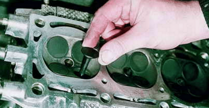
Before starting work, the cylinder head is first cleaned of grease and dirt. Next, it needs to be laid on a workbench with good lighting. After this, you should perform the following operations:
- inserting the mandrel one by one into the holes of the old bushings (from the side of the combustion chamber), carefully strike its end with a hammer and knock out the bushings;
- clean the bushing seat with a rag containing gasoline or solvents, and blow with compressed air;
- the bushings must be kept in the freezer for about 2 days in advance to compress them;
- we heat the cylinder head on an electric stove to a temperature of approximately 100 degrees Celsius (this will expand the landing channels);
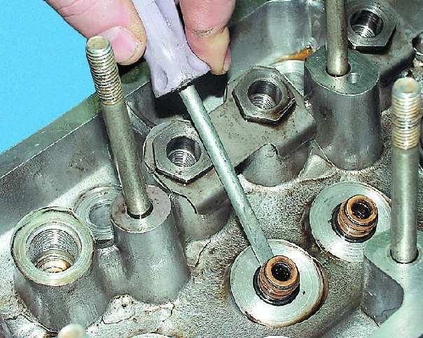
- We put retaining rings on the bushings, insert the bushings into the holes and carefully hammer them through the mandrel until they are completely seated.
Replacement of valve guides ends with modification of the bushing holes to the required diameter. This must be done when the head has completely cooled down. If the valve stem does not fit into the hole in the sleeve, it is bored out with reamers, which are alternately used from the smallest size with fitting on each pass.
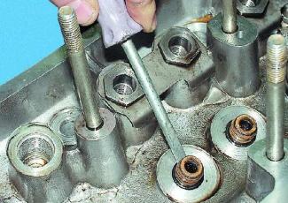
What you should know when carrying out repairs
In order for the VAZ valve bushings to be replaced as expected, it is necessary to determine in advance where the intake and exhaust valves are installed, and also to prepare the bushings. It's difficult to confuse them. The intake valve bushing is shorter in size, and on the inside there are grooves for lubrication that extend to the middle. The exhaust valve bushings are longer and have grooves running the full length of the inside.
A characteristic feature of domestically produced cars is that their repair and Maintenance It is quite possible to do it on your own. The main thing is to have the necessary knowledge, instructions and the desire to cope with the task on your own. But still, in the case of replacing valve guides, which has a number of its own specific features, it is better to carry it out at a service station. However, many motorists cope well with this task in their own garage.
Why do you need a guide bushing?
The guide bushing can quite rightly be considered the main element on which the resource and correct work tandem "saddle - valve plate". The material from which the part is made and its design itself are primarily aimed at working under conditions of high speeds of the valve stem fixed in it, constant high-temperature loads and the almost complete absence of lubrication in the valve-bushing pair.
Causes and consequences of deformation
The described conditions lead to the fact that during engine operation, the valve guide bushing also wears out, which is why, over time, its alignment with the valve stem may be disrupted. Subsequently, the part breaks even more and the valve begins to “walk” and does not fit tightly to its seat, and this, in turn, leads to the chamfer of the seat breaking over time. As a consequence, you can get a burnout of the valve and have to replace the seat.
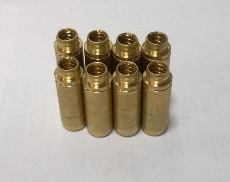
Appearance of bronze guide bushings for VAZ 2108–2109 models
Also, due to the “walking” of the valve in a broken guide, the oil seals can quickly become unusable. They simply will not be able to hold oil with increased angular displacement of the valve stem. The result will be oil getting into the engine, and if you also take into account that more oil will pass through the broken bushing than usual, then the situation will not be pleasant. Carbon deposits on valves and other parts around the combustion chamber will increase, the level of harmful exhaust emissions will increase, and you may end up with a prematurely failed catalytic converter. And a simple replacement valve stem seals There is no way around this, as soon the problem will return again.
Why you shouldn't neglect checking
When repairing an engine, it is better to pay special attention to its head. Often it is this part of the engine that is to blame for the fact that the level of compression in the cylinders is far from the desired level. When repairing cylinder heads, motorists sometimes limit themselves to only grinding the valves to their seats, believing that there is nothing particularly wearable in all-metal bushings. At the same time, checking how large the gap between the part and its valve is will be completely worthwhile. When the obtained clearance figures go beyond those recommended by the car manufacturer, then no amount of grinding in the valves or replacing the valve stem seals will protect against problems in the future.
Materials used to make bushings
For the manufacture of bushings, materials with good wear resistance and thermal conductivity are used. Among these you can find:
- special cast iron alloys;
- bronze;
- brass;
- metal ceramics.
In terms of thermal conductivity and cost, brass, along with bronze, are among the leaders, so the vast majority of bushings are made from alloys of these metals.
Nuances to consider
Most bushings have a special support collar on the outside, designed to ensure proper fixation of the part vertically in the cylinder head. If the part is smooth, then installation is carried out using a special mandrel.
For intake valves, the guide bushings should not protrude so as not to increase the aerodynamic drag of the intake channel. Exhaust valve bushings are designed to “hide” the valve stem as much as possible to protect the latter from high temperatures and better heat dissipation.
Appearance and location of the valve guide in the cylinder head
The manufacturing precision of the bushings is very high. This is necessary to obtain the most accurate alignment and the best fit of the valve plate and seat during engine operation. The outside of the body of the part that is to be pressed into the cylinder head must be processed as cleanly as possible; there should be no scratches or marks on it. This ensures optimal heat removal from this accessory to the block head.
Video: review of valve guides for VAZ 2108–2109
Wear detection
The nature of the operation of the “valve stem - bushing” pair causes increased wear on the inner surface of the latter. It becomes noticeable when the car is driven for a long time (about 150 thousand km). At the same time, the use of low quality oils can significantly speed up the life of the bushings. Therefore, it is always advisable to determine the degree of wear before replacing them. There are two methods for this:
Extraction

Pressing video
Installation of new
- Before installing new spare parts, you need to determine the value of the actual tension. To do this, the diameter of the seat in the cylinder head and the diameter of the bushing are measured. The difference between the first and second should not exceed 0.03–0.05 mm.
- If the socket is noticeably larger than the bushing chosen for it, then you should look for a part with a larger diameter. If the diameter of the socket is insufficient, then you can use the services of a drilling machine to increase it.
- Before pressing in new bushings, the cylinder head must also be heated. But it is generally recommended to cool new spare parts in liquid nitrogen, which will greatly reduce their outer diameter and make it easier to enter into the housings that have expanded from heating, and will also reduce the risk of damage during pressing.
- But since not everyone has liquid nitrogen in their garage, you can first place the new bushings in the freezer. Again, if the latter is available in the accessibility zone. For simplicity, we can take as the required temperature difference between the cylinder head and the guide sleeve equal to 150 degrees Celsius. Even when pressing bushings, it is recommended to lubricate the rubbing surfaces with liquid machine oil, especially if the parts have not been heated/cooled.
- The pressing process itself follows the same scenario as pressing out. As a tool, a mandrel and a hammer (or an air hammer with an attachment). Next, using a series of successive blows, we hammer the part into the seat.
Press-fitting video
Correction of the alignment of the intake manifold, its replacement and prevention. Do not remove more material than necessary to restore a flat contact surface. Some manufacturers limit the allowable total thickness of material that can be removed from the engine block plate and bottom of the head to 0.008 in. (0.2 mm). Removing a layer of material from the bottom plane of the cylinder head of an overhead camshaft engine results in a decrease in the distance between the camshaft and crankshaft. This, in turn, will cause a delay in the opening and closing of the valves if the original distance between the camshaft and the crankshaft is not restored using a special compensation spacer made of copper, which is installed between the cylinder block plate and the sealing gasket.
The valve guide ensures perfect alignment of the valve sealing chamfer with the valve seat in the block head. Valve guides are usually built-in, i.e. are cast together with the head housing. This is done to improve heat transfer and reduce production costs. If the materials of the valve stem and head are incompatible, the guide bushings are made in the form of plug-in (pressed-in) parts.
No matter how good the quality of the valves and valve seats themselves, they will not perform well if the guide bushing is mismatched; both ends of the bushing will become elliptical or egg-shaped. If the valve stem dangles in the guide bushing, then there is no need to check it - and it is clear that it needs to be repaired. The valve guide must be rebuilt to fit the valve that is to be installed in it.
Many automotive engine manufacturers specify standard valve stem-to-valve guide clearance in the range of 0.001 inch to 0.003 inch (0.025 mm to 0.076 mm). However, some vehicle models, especially those equipped with engines with aluminum cylinder heads, may require much wider clearances. For example, in many Chrysler 2.2 L and 2.5 L engines, the standard clearance is set in the range of 0.003-0.005 inches (0.076-0.127 mm). Such a gap may seem too large to auto mechanics accustomed to the usual technical requirements for the size of the gap. Although this clearance may seem excessive, remember that the valve stem expands in diameter as it heats up. Thus, the operating gap is smaller than the gap measured at room temperature. Before you finally decide that the valve guide has excessive wear, check the manufacturer's specifications again.
Car manufacturers usually indicate the following values for the standard valve stem-to-valve guide clearance.
Be sure to check the manufacturer's specifications for the engine being serviced. The exhaust valve has a larger gap than the intake valve because the exhaust valve heats up more and therefore expands more than the intake valve.
Excessive clearance between the valve stem and valve guide causes increased oil consumption. Under the influence of the vacuum created in the intake manifold, oil is sucked into the combustion chamber through the gap in the intake valve guide from the upper surface of the cylinder head into the combustion chamber. The increased valve clearances cause the valves to become hotter than normal because most of the heat stored in the valve is transferred to the cylinder head through the valve guide.
The diameter of a human hair is approximately 0.002 inches (0.05 mm). Thus, the typical clearance between the stem and valve guide is only the thickness of a human hair.
During operation, the valve drive mechanism creates lateral pressure on the top of the valve stem. This is the main reason for wear of the valve stem and guide sleeve. Typically, each time the valve is opened, it rotates slightly around its axis, so it wears evenly around its perimeter. The valve guide bushing is stationary and therefore always wears out in the same place. Eventually there are holes.
Measuring Valve Guide Wear
Before measuring valve guide wear, you must measure the diameter of the valve stem. Next, use a split ring gauge to measure the diameter of the hole in the center of the valve guide. The opening of the ring gauge is then measured using a micrometer. The diameter of the hole at both ends of the guide bushing is then measured.
The cut in the ring during these measurements should be oriented perpendicular to the axis of maximum wear of the hole. The difference between the largest hole diameter in the guide sleeve and the diameter of the valve stem is then calculated. If the gap is greater than the specified limit, the valve guide must be repaired.
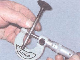
The valve stem-to-valve guide clearance can also be determined by using a dial displacement meter to measure the play of the valve when it is pulled out of the seat. It is also necessary to measure the diameter of the valve stem.
 Most American car manufacturers whose engines use built-in valve guides recommend widening the worn holes in the guides using a reamer and replacing the valves with new ones with stems of increased repair diameter. If the valve guide is worn, the valve stem is likely worn as well. In this case, new valves are required. But if the valves are replaced, then it makes no difference whether they have a standard diameter rod or a repair rod of increased diameter. Repair valves are usually available with stem diameters increased by standard sizes - 0.003, 0.005, 0.015 and 0.030 inches. The hole in the guide bushing to be repaired is reamed or honed to the required diameter corresponding to the diameter of the repair valve stem. The clearance between the stem and the repaired guide bushing remains the same as the old valve. When replacing worn valves with repair ones that have stems of increased diameter, the oil clearance and heat transfer characteristics remain the same.
Many companies involved in engine overhauls, in order to simplify head repairs, use repair valves with rods of increased diameter.
When restoring a hole in a valve guide using knurling technology, the knurling head rotates and moves deeper into the hole. During this operation, the diameter of the hole is reduced by displacing metal from one place to another. Knurling technology is ideal for engines with integral valve guides (i.e. non-removable, cast with the cylinder head and therefore not replaceable). Knurling is not recommended for repairing holes with wear greater than 0.006 inch (0.15 mm). During the knurling process, a conical-shaped knurling roller with a small diameter, or a thread-cutting tool with a specially blunted cutting edge, is pressed into the wall of the hole, extruding a groove in it without removing metal, as shown in Fig. 13.39 and 13.40. The metal is squeezed out onto the edges of the groove, similar to how soft soil is squeezed out of the rut by the wheels of a car onto its edges (forming a continuous protrusion along the edges of the rut). The knurling head is driven by a drill with a reduction gearbox. The reamers included with the knurling head ream the knurled hole just enough to ensure that the valve guide-to-valve stem clearance meets the general remanufactured standards. If special precision is required, the holes are honed to the specified size using high-precision equipment. Valve guides remanufactured by knurling typically have half the clearance of new parts. But such a small gap is acceptable, because after knurling in the wall of the hole, along its entire length, there remain many thin annular projections that hold the oil, ensuring normal lubrication.
Valve Guide Replacement
If the engine valve guides are removable, it is recommended to replace them when repairing the valve assembly. Before dismantling the guide bushing, it is necessary to measure its height so that the new bushing fits into place as expected.
After this, the worn guide bushing is pressed out of the head using a punch. It is a rod that corresponds in diameter to the hole into which the guide bushing is pressed and has a recess at the end, the edge of which presses on the edge of the guide bushing. If the guide bushing has a flange, then it is necessary, taking this into account, to correctly choose which side to press out the guide bushing from. Typically, the guide bushings are pressed out from the combustion chamber side towards the valve rocker arm. The new guide bushing is pressed into the mounting hole using the same punch. It is necessary to ensure that the guide bushing is pressed to the required depth. After replacement, the holes in the repair guide bushings are reamed or honed to the required diameter.