Does the instrument panel on the VAZ 2110 not work? For repairs, you will need a diagram, panel pinout. As with any other model, dashboard"tens" serves to display the state of the car, it shows the amount of fuel, speed, and also informs the owner of the VAZ 2110 about malfunctions in the nodes. But not for all motorists, the panel is an open book, especially for novice drivers. This material describes the pinout, the principle of operation, the purpose of the devices, the main malfunctions, as well as repairs.
Indicators
Dashboard
At the moment of ignition, all the lights on the instrument panel light up, after starting the engine, most of the indicators go out. Sometimes, even after starting the engine, one bulb continues to glow or even blink. This worries drivers, because it is difficult to say which node in the VAZ 2110 car is malfunctioning, diagnostics are required to determine the breakdown.
We know that the “ten” is old or new. In both versions, the designations remain identical, the only difference is the location of the bulbs and their scheme.
At the bottom of the instrument panel there are indicators that signal a malfunction in the operation of various VAZ 2110 systems. If they continue to light when the engine is running, it means that repairs will have to be carried out.
Going from left to right:
- The leftmost bulb located on the instrument panel refers to the air damper - the indicator is present in models with a carburetor engine;
- Oil can icon. If the indicator lights up or flashes, then the oil compression in the power plant has dropped, the pump is malfunctioning;
- Letter "P" inside a circle. The dashboard reports that you forgot to turn off the parking brake;
- A light that indicates a malfunction of the battery or generator. The alternator belt may have broken, an open circuit has appeared, charging is not in progress;
- When the "far" works, the headlight icon lights up on the panel;
- Light bulb icon - the indicator shows the included dimensions;
- "Check Engine" indicator. If it burns, then it is urgent to carry out diagnostics and subsequent repair of the VAZ 2110 engine, serious defects have appeared in the operation of the power plant. The best solution is to stop moving;
- Directly above the sign of a faulty engine is an alarm lamp.
In addition to these indicators, the front part is equipped with a display showing the mileage. Also in this area are the clock and setting keys for them. In the “dozens” of the new generation, the screen may be of a narrow format, but the scheme remains the same.
Additional panel
In cars of the new model, there is an additional panel with useful indicators. A flashing icon depicting a man with a belt tells you to buckle up - this applies to both the driver and his companions. While driving, the wheel icon may light up, it is possible that the pads are worn out, repair is required.
- Oiler lamp - lights up when the oil level drops below normal - you should check the level as soon as possible.
- Windshield washer - he tells us that the washer fluid is almost over.
- The thermometer above the tank indicates an increased temperature of the coolant.
- Crossed out icon with an arrow - the position or brake light does not work.
Dashboard diagram
In the figure above, the connection diagram of the instrument cluster. That is, according to this scheme, you can determine the connection point on the dashboard of a faulty indicator. You will need it if you have to change, for example, a battery warning lamp due to a malfunction. But in addition to the wiring diagram, you also need the pinout diagram, which is described below.
Pinout
If you want to perform repairs or other operations on the instrument panel, then you need a VAZ 2110 pinout. If it is not available, you will have to track each wire from the indicator, button to the device. The scheme allows you to determine which of the devices does not work in the event of a malfunction in a particular node. If the indicators in the old and new VAZ 2110 are identical, then the pinout is slightly different. There are two pads - red and white. Pinout only at the beginning can seem complicated. Let's take a few connectors as an example.
Under the first number is the black wire that goes to ground. The thirteenth number is tied to the oil pressure sensor in the system, as the circuit also tells us. The white block indicates the connector number, wire and node (unit) to which the wiring goes. The red block is read in exactly the same way. The first connector contains blue and red wires, they go to the external temperature sensor. As for the thirteenth number, here the white wire leads to the ignition switch.
The pinout and circuit shown in this article are basic. They may differ in color coding, because many variations of the VAZ 2110 have entered the market. In order not to get confused, it is recommended to compare the data from the article with the instruction manual, where there is also a diagram and pinout.
Faults and repairs
Instruments or indicators may fail. It can be part of the indicators or even the entire speedometer. Owners of the VAZ 2110 rarely encounter such a situation, since the dashboard is working properly, especially in domestic cars. Before changing the instrument panel or repairing individual parts, you should make sure that the sensors are working - we use on-board computer.
Inaccurate installation leads to failure of the elements. On the dashboard board, the parts are fastened with simple rivets, hence the negative result. Vibrations are constantly acting on the body, so the installation simply “falls apart”, breaks appear in the chain. Repair in this case is the soldering of the rivets and a thorough cleaning of the contacts.

After soldering is completed, the dashboard can be returned to its place. If you have free time, you can go through the sandpaper on the contacts. On older cars, they usually oxidize, which can prevent the instruments from functioning properly.
You can see how to remove the dashboard in the video below.
Instrument cluster VAZ 2110-11-12: All vehicle control devices are combined into a instrument cluster. It includes: electronic speedometer and a tachometer, coolant temperature gauge, fuel gauge and 12 warning lights. The instrument cluster is fixed in the instrument panel socket with two screws. Dashboard combinations are produced by schetmash, Kursk and VDO. In addition, on the VAZ 2110, you can install the instrument panel from the VAZ 2115 (with two windows), the instrument panel combination will display the correct information. In addition, there are combinations of the instrument panel with a mechanical odometer.
Wiring diagram of the instrument cluster VAZ 2110 2111 2112 (view from the back of the instrument cluster)
|
Fig 1 pinout of the instrument panel combination VAZ 2110 |
|
| 1
– A control lamp of a reserve of fuel; 2 – lamps of illumination of a combination of devices; 3 – a control lamp of the right turn; 4 – A control lamp of the left turn; 5 - block of plugs; 6 – the index of temperature of a cooling liquid; 7 – a control lamp of external lighting; 8 – A control lamp of the air gate of the carburettor; 9 – a control lamp of pressure of oil; 10 – A control lamp of a parking brake; |
11
– a control lamp of a charge of the rechargeable battery; 12 - tachometer; 13 – control lamp «CHECK ENGINE»; 14 - speedometer; 15 – a control lamp of level of a brake liquid; 16 – a control lamp of the alarm system; 17 – control lamp high beam headlights; 18 - fuel gauge. Plugs 2, 3 , 8 , 9 in a block X2 are the outputs of the speedometer 14 |
Instrument combination. All control devices of the car are united in a combination of devices. It includes: electronic speedometer and tachometer, coolant temperature gauge, fuel gauge and 12 warning lights. The instrument cluster is fixed in the instrument panel socket with two screws.
The connections of the instrument cluster are made by printed wiring on a foil-coated getinax board. The board is fixed on the back side of the case. The scheme of connections of a combination of devices is given on fig. , plug addresses in table "Addresses of output plugs of the instrument cluster"
The speedometer has two counters of the distance traveled: one is total, and the second is “daily”. The readings of the daily counter can be set to zero by the button located on the instrument cluster itself. The daily counter can only be reset when the vehicle is stationary.
On a part of produced cars it can be installed electronic combination appliances. It contains the same instruments and indicator lamps as the conventional instrument cluster. You can check the instrument cluster only on a stand in a specialized workshop. The instrument cluster is not repairable.
Display unit of the onboard control system. The unit contains an electronic control circuit with a sound signaling device and 10 LED signaling devices: insufficient oil level, insufficient coolant level, insufficient washer fluid level, faulty outdoor lamps, unfastened seat belts, wear brake pads front brakes and four open door alarms. The block plug addresses are given in table "Addresses of the output plugs of the display unit of the on-board monitoring system" The order of conditional numbering of the plugs of the block is similar to the order of numbering of the plugs in the blocks of the instrument cluster (see fig. Connection diagram of the instrument cluster (view from the back)).
Addresses of output plugs of the instrument cluster
|
Plug |
Block address |
|
|
white (X1) |
red color (X2) |
|
|
Housing ("mass") |
To the "W" terminal of the fuel gauge sensor |
|
|
Low voltage tach input |
||
|
High voltage tachometer input |
Housing ("mass") |
|
|
Spare |
To the instrument lighting switch |
|
|
To coolant temperature sensor |
To turn signal switch (starboard side) |
|
|
To fuse F1 of the mounting block |
To turn signal switch (left side) |
|
|
To brake fluid level sensor |
||
|
To motor controller |
To on-board computer |
|
|
To fuse F19 ("+" power supply) |
To speed sensor |
|
|
To fuse F19 ("+" power supply) |
To the "T" terminal of the fuel gauge sensor |
|
|
To parking brake switch |
To fuse F3 of the mounting block |
|
|
To the output "D" of the generator |
To the hazard switch |
|
|
To oil pressure warning light sensor |
To terminal "50" of the ignition switch |
|
Addresses of the output plugs of the display unit of the on-board monitoring system
|
Plug |
Address (assignment) to plugs |
|
To fuse F19 ("+" power supply) |
|
|
Housing ("mass") |
|
|
To lamp health relay |
|
|
To ignition switch microswitch |
|
|
To the ceiling |
|
|
To rear left door sensor |
|
|
To rear right door sensor |
|
|
To oil level sensor |
|
|
To coolant level sensor |
|
|
To washer fluid level sensor |
|
|
To seat belt sensor |
|
|
To brake pad wear sensor |
|
|
To front left door sensor |
|
|
To front right door sensor |
* On right-hand drive vehicles, plug 2 is connected to ground.
Odometer correction on the instrument panel combination VAZ 2110 2111 2112 2113 2114 2115
Special devices can be used to correct the odometer, but they are often specialized and not available to most. As an alternative to these devices, you can implement the correction of mileage readings by following the following recommendations.
The odometer is actually a pulse counter powered by a speed sensor. If a certain frequency is observed and applied to the terminals of the instrument panel combination, the odometer readings can be corrected.
In particular, a pulse with a frequency of 200Hz corresponds to a car speed of 120km/h. The increase in the frequency of the pulses is not linear, so at a frequency of 2500 Hz, the speed will be 1120 km, while the speedometer needle will simply show the maximum speed.
The pulses supplied to the output (terminal 9 of the red block, see the figure below) of the instrument panel combination for mileage correction must be rectangular. The easiest way to implement pulse generation is through a computer sound card, that is, actually feeding sound from the computer output to the instrument cluster, while limiting the sound to a minimum and not using amplifiers in order to prevent a high signal level. Subsequently, raise the sound level until the instrument panel starts counting the kilometer, that is, the odometer correction begins. For the formation of impulses, it is better to use the program, it can be downloaded from any radio site on the Internet. In addition, a necessary requirement is the power during the correction of the odometer mileage and the instrument cluster itself. As a result, observing all the above requirements, make connections according to the following scheme.
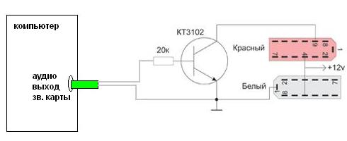
Figure 2 Scheme for adjusting the odometer on the instrument panel combination VAZ 2110 2111 2112 2113 2114 2115
The KT3102 transistor can be replaced with any high-frequency transistor with a similar structure, for example KT315.
Now you can adjust the mileage, odometer kilometer and at home!
Be careful when connecting, do not reverse the contacts and polarity, in order to avoid damage to the electrical part of the instrument panel combination.
When changing the "instrument cluster illumination", it is important to know what the "instrument cluster" contacts are responsible for. Because Some lamps are responsible for the malfunction of the car. But before changing the backlight, it was important for me to know that the "parking brake" (handbrake) and "alarm" lamps work for me. I have a tidy company "AP" (not ice), when checking, I found out that the handbrake lamp is working (as a result, a wire break coming to the limit switch under the handbrake), and there was no alarm lamp (soldered and EVEN works).
An example of a VDO panel.
The location of the lamps on the instrument panel:
1, 5, 7, 8, 20 - backlights;
2 - socket for connecting the red block of the wiring harness;
3 - control lamp of indicators of the right turn;
4 - control lamp of indicators of the left turn;
6 - socket for connecting the white block of the wiring harness;
9 - reserve socket (airbag warning lamp);
10 - control lamp of emergency oil pressure;
11 - control lamp for turning on the parking brake;
12 - generator malfunction indicator lamp;
13 - control lamp for turning on the alarm;
14 - control lamp for a malfunction of the engine management system;
15 - odometer display backlight;
16 - control lamp for switching on the main beam of headlights;
17 - control lamp of insufficient level of brake fluid;
18 - control lamp for switching on external lighting;
19 - a control lamp of a reserve of fuel
I found the pinout of the instrument panel in Johns0n's BZ, for which many thanks to him, but I redid the pinout for myself, something closer to the standard. There is another good article from bounce1986.
Red block:
1 - if the tidy is simple (without microcircuits, etc.), then connect to the blue-red wire (fuel reserve lamp), if there is a display under the tachometer, then connect to the temperature sensor (take from VAZ-2114, one contact to the tidy , the other to ground, put either in the passenger compartment or in the engine compartment, but so far from the engine and so that the wind does not blow).
2 - speed signal output to the on-board computer. If it is, then take the speed signal from this contact.
3 - to the speed sensor.
4 - fuel gauge, connect to the pink-red wire. (I didn’t test anymore, because I burned the lamp and had to re-solder)
5 - high beam signaling lamp, connect to the green-black wire; “–” from 9th contact.
6 - alarm lamp, will light up when “+” is applied; “–” from 9th contact.
7 - checking the brake fluid level indicator lamp. If you apply “+”, then the brake lamp will light up; “–” from 9th contact. It can be connected to the red wire of the ignition switch, then, just like on the 2110/2114, the lamp will be checked when the starter is turned on.
8 - power supply of devices, connect to the orange wire.
9 - ground, connect to the black wire, common "-".
10 - instrument panel illumination, connect to a white wire, it will light up when “+” is applied; “–” from 9th contact.
11 - right turn indicator lamp, connect the pads of the steering column switch to the blue wire, it will light up when “+” is applied; “–” from 9th contact.
12 - left turn indicator lamp, connect the pads of the steering column switch to the blue wire, it will light up when “+” is applied; “–” from 9th contact.
13 - brake fluid level indicator lamp, connect to a pink-blue wire, it will light up when “+” is applied; “–” from 9th contact.
White block:
1 - ground, connect to a black and white wire, common “-”.
2 - ECM signaling lamp (Check engine or “faucet”), will light up when “-” is applied; “+” with 4 pins.
3 - (if you look at the description in Johns0n's BZ, then “2” and “3” go to the ECM lamp. If the car is injection, then connect one of the contacts to the orange wire and the other to the remaining one, I do not connect this contact when checking , because I don't see the result)
4 - power supply of devices, connect to the orange-blue wire.
5 - hand brake warning lamp, connect to the brown wire, it will light up when “-” is applied; “+” with 4 pins.
6 - battery charge indicator lamp, connect to a brown-white wire, it will light up when “-” is applied; “+” with 4 pins.
7 - warning lamp low pressure oil, connect to the gray-blue wire, lights up when “-” is applied; “+” with 4 pins.
8 - low-voltage tachometer input (from the ECM), connect to the brown-blue wire
9 - high-voltage input of the tachometer (from the coil), connect to the brown-blue wire.
10 - if there is a display under the speedometer, then connect to the red-white wire at the brake light switch.
11 - coolant temperature gauge, connect to the green-white wire.
12 - outdoor lighting indicator lamp, connect to the yellow wire, it will light up when “+” is applied; “–” from 1 contact.
13 - carburetor air damper cover lamp, connect to a gray-orange wire.
Probably, hardly anyone will argue with the fact that the VAZ "ten" is not the pinnacle of design thought. However, there is nothing surprising here, because this car was designed in the last century. At the same time, the compensator, and quite serious, in this case is the price. In other words, a certain compromise is offered - the imperfection of the car in exchange for an acceptable cost. Well, the choice is ultimately made by the car owner himself, deciding whether this option suits him.
The advantages and disadvantages of this model can be discussed for a long time. However, this is not what we are talking about now. Those who decide that the "ten" is a suitable option in terms of price and quality, during the operation they often want to ennoble their iron horse, making changes both to the exterior and to the interior.
If we talk about tuning the interior of a car, then one of the main objects of improvement here is the dashboard. Many simply do not like the native version, which, frankly, does not look very attractive. Yes, after the "Zhiguli" this is an undoubted step forward, but after all, the 21st century is already outside the window, and I want something more beautiful and pleasing to the eye.
Why you need to know the pinout
But before proceeding with this kind of upgrade, you need to understand which of the wires leads where. The pinout of the instrument panel of a VAZ-2110 car is a very important point in “tuning”. Without this, you run the risk of getting confused in a sufficiently large number of wires, buttons and various sensors. The pinout is useful in any case - both when making minor improvements, and when completely replacing the instrument panel.
The process of installation and dismantling itself is quite laborious, but if you know the correct sequence of actions, then there is nothing particularly difficult about it.
For these works, you will need a minimum set of tools - a screwdriver and pliers.
For those who do this for the first time, it is best to stock up on self-adhesive pieces of paper, like those on which prices are written in stores, and a pen. With their help, at the time of disassembly, you will indicate, firstly, the sequence of dismantling parts, and secondly, which of the wires is connected to where. At first glance, this takes time, but in fact, for beginners, such marking will help to quickly assemble the panel back.
At the same time, before starting work, it is best to stock up on a pinout diagram - at least conditional. Indeed, in the process of work, you need not to confuse anything and correctly deal with each wire and connection in the process of reassembly. It is worth noting one very important point. By and large, understanding the pinout of the panel of the "tenth" family will not be difficult even for a beginner.
But at the same time, it must be remembered that there are certain differences here, depending on the plant where the car was manufactured and on the year of its release. For example, the instrument panel may be of an old design, with a mechanical odometer. If the odometer is electronic, then this is a newer version. Accordingly, there are certain differences in the pinout between these panels.
Which wire leads where?
First, let's look at the back of the instrument panel. At the top are:
- fuel gauge;
- shield lighting lamps;
- control of the right and left turns (separately);
- tachometer;
- block with many plugs;
- coolant temperature gauge.
As you can see, there really is nothing particularly complicated here. At the bottom of the instrument panel on the back side are the controllers:
- high beam;
- "emergency";
- CHECK ENGINE;
- battery charge;
- parking brake;
- oil pressure;
- air damper (for models with a carburetor);
- outdoor lighting work.
In addition, there is also a speedometer and a brake fluid level indicator lamp.
Now let's take a closer look at the pads. There are two of them - white and red. In the first, the connectors and wires look like this (in order):
- Bulk black wire.
- Red-brown - low-voltage supply from the ECU to the tachometer.
- Yellow - high voltage supply to the tachometer from the coil.
- Red-blue - comes from the battery through the 6th Const fuse with a voltage of 12 volts.
- Green-white - leads to the coolant temperature sensor.
- Green-yellow - fuse F1, responsible for the parking lights.
- This connector has no color, it goes to the throttle valve.
- Red-white - leading to the CHECK ENGINE signal light.
- 2 orange wires leading to two F19 + 12 volt power fuses.
- Similar to the previous connector.
- 2 wires of blue-brown color, following to the terminal "VK" of the handbrake.
- The output to the terminal D of the generator is a brown-white wire.
- Gray with blue - wire going to the oil pressure sensor.
In the red block, the account number of the connector, the color of the wires and the devices they lead to look like this:
- Red-blue - leads to the external temperature sensor.
- Orange - follows the power fuse F19 + 12 volts.
- 2 ground wires in black.
- White - leads to the instrument lighting switch.
- Blue - to the right turn indicator.
- Blue-black - to the left turn indicator.
- Blue-pink - to the brake fluid level sensor.
- Brown - leads to the on-board computer.
- Gray - to the speedometer.
- Pink - to the fuel gauge.
- 2 green/black wires leading to F3 high beam fuse.
- Blue-white - to the alarm switch.
- White wire leading to terminal 50 - ignition switch.
 It is worth noting here that the most typical and common pinout scheme is given above. However, different manufacturers may have differences in color coding. For example, in the instrument panel manufactured by the Kursk "Schetmash" there will be minor differences from the above diagram, in particular in the red block (connector number and wire color):
- black;
- red-brown;
- yellow;
- red-white;
- green-white;
- 2 brown wires;
- empty;
- red-white;
- blue;
- orange;
- blue-brown;
- white-brown;
- blue grey.
As you can see, there are still some differences, even if they are small. However, these little things are very important. Therefore, it is best, before starting work, to find out which panel your car has (by year of manufacture and manufacturer), and then find the correct pinout diagram. However, there is another option - the self-adhesive papers already mentioned above. When disconnecting the wires, be sure to label them - this will greatly facilitate the assembly process.